Cattron™ MP96/48 Series Portable Remote Control Systems
User Manual
47
68C-MP96/48-RD-EN
Version 006
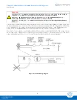
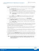
3. Using a small screwdriver, rotate the selector switch to the desired position.
4. Replace the lid on the Gold Box.
5. Restore power to the receiver/decoder by turning on the circuit breaker on the bottom of the Gold Box.
6. Close the cover of the receiver/decoder.
5.5
Post Installation Checks
Having installed your MP Series System, and before starting its operation, carry out a full
in
accordance with the procedures described in the following section of this manual.
Before
for the first time, we recommend that you familiarize yourself with
the
System Status Display and LED Indicators
described and illustrated in the following paragraphs.
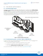
5.5.1 System Status Display and LED Indicators
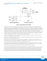
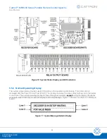
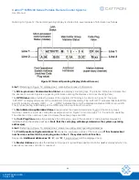
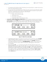
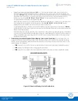
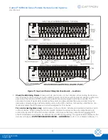
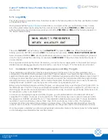
Referring to Figure 10, the System Status Display consists of two lines of text with up to 24 characters on each
line, located on the decoder circuit board and viewed through the window of the electronic chassis. This display
provides a source of information that has been collected from various test points throughout the system. The
information displayed includes the following:
•
Power on message and test results during system power initialization
•
Specific machine custom events or conditions identified by the customer and designed into the system
engineering, e.g., low air pressure input
•
Normal internal events of the MP96
– electronic components and software operation
•
Hardware related failures that may occur on the decoder board
•
Incoming data messages and bit errors that may occur due to transmission problems
•
Interfacing hardware output failures showing which devices or modules have failed
•
Snapshots of system activity
– both the controller commands and decoder outputs
The most critical monitoring performed by the MP96 is the Automatic Safety Override (ASO) circuitry.
An ASO
error occurs when no input command is received, but an output is active
. The status display will identify by
name the output that
failed ‘ON’, followed by the motor group main contactor that is being shut down (stage one)
and what functions are included in that group. Continued operation of other functions which are not in that group
will remain. If
shutting down a specific motor group fails to clear the error, the entire system (stage two) will be
disabled.
The MP96 also checks for loop failures throughout the system and machine interfaces. A loop failure can be
described as the opposite of the ASO failure. A loop fault is sensed if an input command is active for a given
function, but there is no output sensed to be on. This test checks for continuity in the output and input monitoring
circuit.


