Cattron™ MP96/48 Series Portable Remote Control Systems
User Manual
18
68C-MP96/48-RD-EN
Version 006
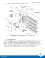
Table 1 provides details about several of the components identified in Figure 1.
Table 1: Receiver/Decoder Components
Component
Description
Electronics chassis
(Gold Box)
The enc
losure, commonly known as the ‘Gold Box’ due to its gold anodized coating,
contains the receiver and decoder circuit boards along with the power supply for the
entire receiver/decoder. For ease of repair, the entire Gold Box can be quickly swapped
out with a spare and returned to Cattron for repair.
Relay output board(s)
The relay output board(s) provide a common connection point for all user connections
to the output relays. The MP96 system has provision for up to 96 relay outputs and up
to 48 inputs, depending on system requirements.
Receiver
The receiver contains the electronic circuits that perform the radio reception functions.
Several LEDs mounted on the receiver circuit board indicate the status of the radio
communications link with the controller.
Decoder
The decoder contains the electronic circuits and microcomputers that control system
functions. This includes checking the address of incoming signals, interpreting the
controller’s commands and controlling the status of the output relays.
Antenna
The connected antenna provides radio reception for the receiver/decoder. Three
antennas may be installed in a ‘triple diversity antenna configuration’.
Power supply module
The power supply module inside the Gold Box provides all required power for the
receiver/decoder. This module also contains an over voltage/under voltage board with
factory pre-programmed setpoints. The power supply module requires 115 VAC at
50-60 Hz.
The receiver/decoder can also be supplied directly with 12 VDC nominal (13.5 VDC).
Other AC or DC supply voltages are available upon request. Contact Cattron at
4.4
Principle of Operation
Referring to Figure 2, the target receiver/decoder is controlled by a remote controller. Provided the correct
address and frequency is programmed into the controller, the controller transmits signals to the receiver/decoder
using a radio link. The signal is picked up by the antenna and passed on to the receiver. If the received signal is
the correct frequency and passes all required data tests, the signal is passed on to the decoder.
The decoder compares the address code of the signal with its own programmed address code.
If the signal’s
address code does not match the decoder’s address code, it is ignored and a message is displayed on a system
status display located in the receiver/decoder unit. If the address code is correct, the decoder processes the
message and energizes and de-energizes the appropriate relays.


