Cattron™ MP96/48 Series Portable Remote Control Systems
User Manual
39
68C-MP96/48-RD-EN
Version 006
When switching the transfer switch between remote and manual control, observe the following precautions:
•
Do not transfer control of a crane with a load lifted; always set down all loads prior to changing the
position of the transfer switch
•
If the crane is equipped with a magnet, set it in the drop position prior to changing the position of the
transfer switch
•
When p
rovided, set the STOP switch on the Portable Remote Controller to ‘STOP’ and the ON/OFF
switch on the Portable Remote Controller to ‘OFF’
5.2.6 Relay Outputs
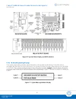
Each relay on the relay output board is completely independent of all other relays. There are no common
connections between any output contacts. This allows the connection of different power sources, AC or DC, to
each separate relay.
Each output relay is typically solid state but may be electro-mechanical as determined by the Cattron
application
engineer for a given control voltage requirement. All relay outputs are individually fused at 5 A. Critical and
directional outputs have accompanying input sense modules that sense the
‘ON/OFF’ state in order to provide
input data to the decoder for ASO verification purposes. Normally Closed and mechanically latching relays are
optionally available. A maximum of six
proportional ‘volt free’ potentiometers are available in lieu of single
ON/OFF outputs.
5.2.7 R/C Snubbing
R/C snubbing circuits are provided on all relay outputs. These snubbing circuits provide protection for each relay
contact when it is connected to an inductive load.
Note:
On some high-impedance loads, such as PLCs or VFDs, small leakage current (approximately 200 µA
at 115 VAC) may present a problem. If this is the case, the snubbing circuit may be removed by cutting
out either the resistor and/or capacitor located next to the affected relay.
5.2.8 Mainline Circuit (Operate and Reset Relays)
WARNING
ALL EQUIPMENT MUST HAVE A MAINLINE (ML) CONTACTOR INSTALLED AND ALL TRACKED
EQUIPMENT (I.E., CRANES) MUST HAVE A BRAKE INSTALLED.
THE REMOTE CONTROL OPERATE (OPR) RELAYS MUST BE CONNECTED TO THE MAINLINE
SO THAT STOP COMMANDS OR FAULT CONDITIONS MONITORED BY AUTOMATIC SAFETY
OVERRIDE (ASO) CIRCUITRY WILL DE-ENERGIZE THE MAINLINE CONTACTOR AND SHUT
DOWN THE CONTROLLED EQUIPMENT.
FAILURE TO COMPLY WITH THE ABOVE WARNING MAY RESULT IN SERIOUS INJURY OR
DEATH TO PERSONNEL AND DAMAGE TO EQUIPMENT.
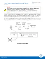
Referring to Figure 4, the Operate (OPR) relay outputs are special. They should always be connected in series
with the mainline (ML) contactor. If a fault were to occur with any one of the ASO monitored critical or directional
output relays, the ‘OPR’ relays controlling the mainline contactor would safely bring the equipment to a ‘STOP’.
This makes the use of a mainline contactor
mandatory
for safe operation of this equipment.
!


