Case IH RBX443 Repair Manual Download Page 86

SECTION 35 - HYDRAULIC SYSTEM - CHAPTER 1

35-4

OVERHAUL

LIFT CYLINDER

Removal

1. Close the tailgate and remove all pressure from

the system by stopping the tractor engine. Then

move the tractor remote control lever several

times to both the open and close positions.

2. Clean the areas on and around the cylinder, 1,

near the fittings that attach the lines or hoses to

the cylinder.

3. Disconnect the lines from the fittings on the

cylinder. Loosen the lines slowly to allow the

release of any residual pressure. Plug the hoses

and fittings.

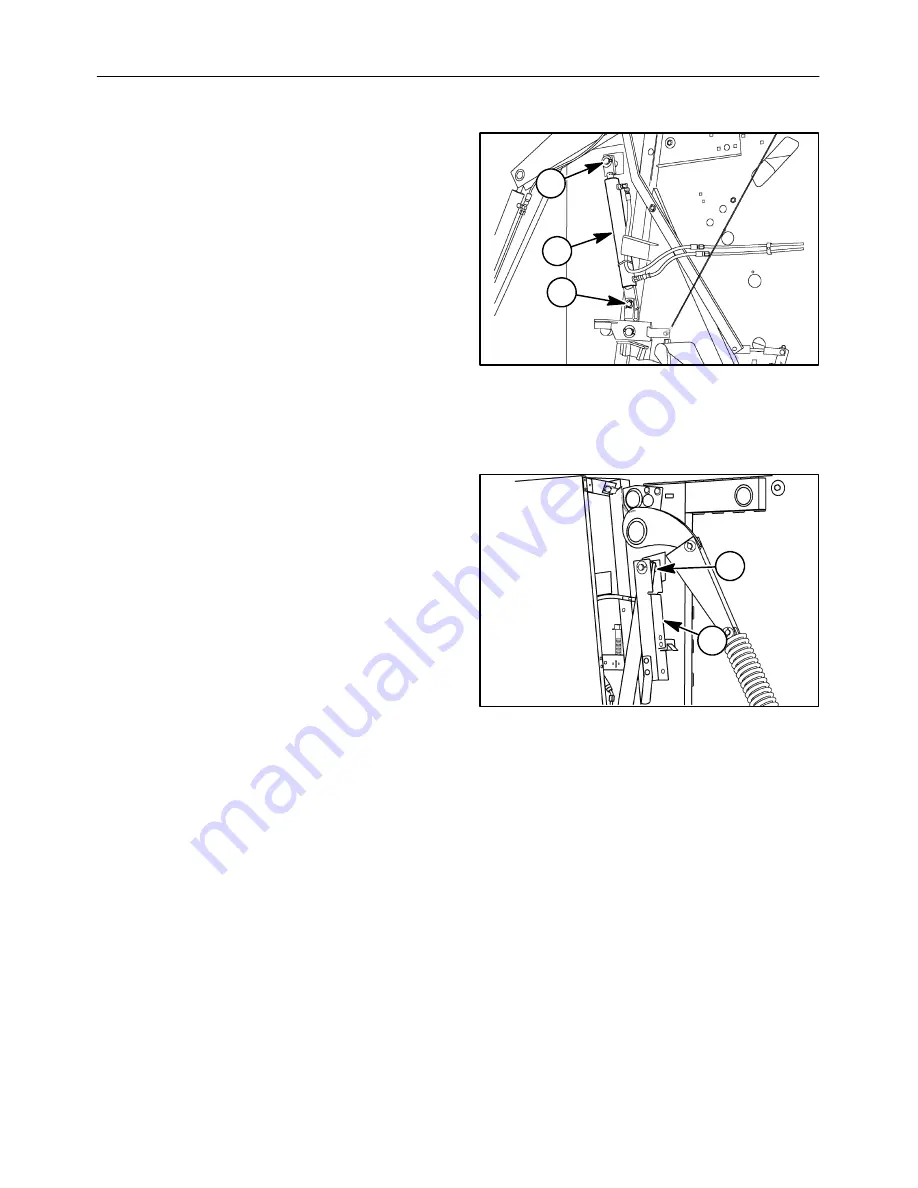
4. Remove the cotter pin closest to the baler from

the lower cylinder mounting pin, 2, in the tailgate

latch. Pull the pin out of the cylinder and latch.

2

3

19993371

1

2

5. Remove the cotter pin and washers from the

upper cylinder mount, 3, and remove the

cylinder. This will also require removal of the

tailgate lockout bracket, 4, and a spacer, 5,

between the rod and lockout.

6. If the cylinder is being replaced, remove the

fittings from the cylinder so they can be installed

on the replacement cylinder.

Installation

1. If the cylinder is being replaced, install either the

fittings removed from the old cylinder or new

fittings.

2. Install the cylinder on the upper mount, 3, and

install washers and a cotter pin to secure the

cylinder.

NOTE:

Be sure to reinstall the tailgate lockout

bracket, 4, with a spacer, 5, on the outside of the rod

when installing the cylinder. There should also be a

41.2 mm (1-5/8

) ID washer between the lockout and

the tailgate and a 35 mm (1-3/8

) ID washer between

the rod and tailgate pin.

3. Insert the cylinder in the tailgate latch and install

the pivot pin, 2, Figure 3, and secure with a 1/4

x 1-1/2

cotter pin.

Connect The Lines To The Fittings

Connect the baler to a tractor and open and close the

tailgate several times to purge air from the system.

Check for leaks at the fittings.

5

4

19993368

3

Summary of Contents for RBX443

Page 1: ...5 5RXQG DOHU 5HSDLU 0DQXDO...

Page 2: ...52 8 7 1 6 7 21 35 66 1 6 7 21 7 1 7KH VHFWLRQV XVHG WKURXJK RXW DOO DVH SURGXFW 5HSDLU PDQXDOV PD QRW EH XVHG IRU HDFK SURGXFW DFK 5HSDLU PDQXDO ZLOO EH PDGH XS RI RQH RU VHYHUDO ERRNV 7KH VHFWLRQV O...

Page 3: ...zed Fluid Lines 7 Use Care Around High pressure Fluid Lines 7 Safe Service Procedures 7 Safety Decals 8 Technical Information 12 Hardware 12 Minimum Hardware Tightening Torques 13 Thread Locking Compo...

Page 4: ...llation 10 Rear PTO 11 Removal 11 Disassembly 11 Assembly 13 Installation 15 Shear Bolt Hub 16 Shear Bolt Hub Bearing Balls 16 Replace 16 Slide Collar Quick Disconnect 17 Disassembly 17 Replace 17 SEC...

Page 5: ...YSTEM Chapter 1 Hydraulic System CONTENTS Section Description Page General Procedures 2 Description of Operation 3 Overhaul 4 Lift Cylinder 4 Removal 4 Installation 4 Disassembly 5 Inspection 6 Assemb...

Page 6: ...g the Electrical Electronic Systems During Charging or Welding 3 Special Tools 4 Troubleshooting 5 Test Procedure 1 Continuity Test for Open Circuits 6 Test Procedure 2 Continuity Test for Short to Gr...

Page 7: ...Power Plug 7 Light Module 8 Baler Lights Wiring Diagram 9 SECTION 60 PRODUCT FEEDING Chapter 1 Standard Pickup Assembly CONTENTS Section Description Page Overhaul 2 Finger 2 Replace 2 Cam Bearing 2 R...

Page 8: ...S Section Description Page Sectional Views 2 Overhaul 3 Floor Roll 3 Removal 3 Inspection 4 Assembly 5 SECTION 62 PRESSING Chapter 2 Starter Roll CONTENTS Section Description Page Sectional Views 2 Ov...

Page 9: ...Tension 3 Overhaul 4 Drive Roll 4 Removal 4 Inspection 5 Installation 5 Adjustment 6 Idler Rolls 7 Rolls 14 18 19 20 and 23 8 Removal 8 Roll 21 8 Removal 8 Inspection All Idler Rolls 10 Assembly 11 R...

Page 10: ...nalysis 3 Overhaul 7 Belt Tension Removal 7 Laced Belt 7 Removal 7 Replace 8 Installation 11 Belt Tracking 13 SECTION 62 PRESSING Chapter 5 Sledge Rolls CONTENTS Section Description Page Sectional Vie...

Page 11: ...age Description of Operation 2 Adjustments 2 Drive Chains 2 Wrapper Arm 3 Twine Knife 4 Overhaul 4 Drive Motor 4 Removal 4 Inspection 4 Installation 4 Twine Arm Drive 5 Removal 5 Inspection 5 Installa...

Page 12: ......

Page 13: ...Near Pressurized Fluid Lines 7 Use Care Around High pressure Fluid Lines 7 Safe Service Procedures 7 Safety Decals 8 Technical Information 12 Hardware 12 Minimum Hardware Tightening Torques 13 Thread...

Page 14: ...h Accordingly anyone who departs from the instructions provided in this manual must first establish that their personal safety the safety of others and the integrity of the machine will not be com pro...

Page 15: ...and right are determined by standing behind the unit looking in the direction of travel The descriptions and specifications contained in this manual were in effect at the time the book was re leased f...

Page 16: ...voided could result in death or serious injury The color associated with Warning is ORANGE CAUTION This word CAUTION indicates a potentially hazardous situation that if not avoided may result in minor...

Page 17: ...taillights are operating properly Operating the Round Baler 1 Read the operator s manual before operating the round baler 2 Only allow properly trained persons to operate the round baler 3 Allow only...

Page 18: ...caping hydraulic fluid under pressure can penetrate the skin causing serious injury Do not use your hand to check for leaks Use a piece of cardboard or paper Stop the engine and relieve the pressure b...

Page 19: ...t or dam aged when heat goes beyond the immediate flame area USE CARE AROUND HIGH PRESSURE FLUID LINES Escaping fluid under pressure can penetrate the skin causing serious injury Avoid the hazard by r...

Page 20: ...king with you Please take this manual and walk around your machine to note the content and location of these warning signs Review these warning signs and the operating instructions detailed in this ma...

Page 21: ...SECTION 00 GENERAL INFORMATION CHAPTER 1 00 9 11 1 8 7 7 3 4 6 10 40013482 3968 06 3967 09 3967 03 4 2 9...

Page 22: ...65 2 Warning Before operating machine read the Operator s Manual and all safety instructions Part 86622073 6 5 5 Danger Rotating driveline contact can cause death Part 849471 6 Warning Keep hands away...

Page 23: ...9 Warning The surface is not intended as a personnel platform Individuals may slip and fall causing serious injury or machine damage Part 86611825 12 13 12 Danger Engage tailgate lock before working...

Page 24: ...s The other 10 is used to tension stretch the bolt After assembly the frictional forces disappear which is the basis for the saying If it does not fail dur ing assembly it will not fail in service The...

Page 25: ...M24 411 303 531 392 648 478 839 619 897 662 1160 855 572 422 NOTE Torque values shown with are inch pounds IDENTIFICATION HEX CAP SCREW AND CARRIAGE BOLTS CLASSES 5 6 AND UP MANUFACTURER S IDENTIFICA...

Page 26: ...16 13 115 17 149 20 178 26 229 28 250 37 324 17 5 155 25 220 5 16 1 4 6 2 55 8 1 72 9 7 86 13 112 14 121 18 157 8 5 75 12 2 109 1 4 MINIMUM HARDWARE TIGHTENING TORQUES IN NEWTON METERS FOOT POUNDS FO...

Page 27: ...d 6 mm 10 mm 8 mm 13 mm 10 mm 17 mm 12 mm 19 mm 14 mm 22 mm 16 mm 24 mm 18 mm 27 mm 22 mm 32 mm 24 mm 36 mm THREAD LOCKING COMPOUNDS Grade Color Loctite Permabond Hernon Nut blue 242 MM 115 423 Stud r...

Page 28: ...81 95 60 70 14 22 2 7 8 1 316 12 122 136 90 100 95 109 70 80 16 25 4 1 1 5 16 12 149 163 110 120 108 122 80 90 20 31 8 1 1 4 1 5 8 12 190 204 140 150 129 158 95 115 24 38 1 1 1 2 1 7 8 12 217 237 160...

Page 29: ...in normal conditions Adjust the intervals for operating in adverse environmental and working conditions The intervals should be shortened for sandy dusty and extremely hot operating conditions CAUTIO...

Page 30: ...8 93 L AKCELA AW68 HYD FLUID B505690 5 G 18 93 L AKCELA AW100 HYD FLUID 339852A1 5 G 18 93 L AKCELA HYDRAULIC EXCAVATOR FLUID B17639 5 G 18 93 L AKCELA TCH FLUID 139030A1 1 G 3 785 L B53977 5 G 18 93...

Page 31: ...ustration Measure as closely as possible from the center of one pin to the center of another The more pitches pins contained within the measurement increase the accuracy If the measured value exceeds...

Page 32: ...54 1778 70 1828 72 80P 1016 40 1047 41 1 4 1270 50 1308 51 1 2 1524 60 1568 61 3 4 2032 80 2095 82 1 2 90P 1143 45 1177 46 3 8 1428 56 1 4 1473 58 1714 67 1 2 1765 69 1 2 2286 90 2355 92 3 4 100P 1270...

Page 33: ...1 US quart 0 9464 liters 1 UK bushel 36 3687 liters 1 UK quart 1 1365 liters 1 US gallon 3 785 liters 1 UK gallon 4 5461 liters 1 barrel 158 987 liters 1 acre 0 4047 ha 1 pound 0 4536 kg 1 hp 0 736 k...

Page 34: ...2 VOLUME inches3 X 16387 millimeters3 mm3 X 0 000061 inches3 inches3 X 16 387 centimeters3 cm3 X 0 06102 inches3 inches3 X 0 01639 liters L X 61 024 inches3 quarts X 0 94635 liters L X 1 0567 quarts g...

Page 35: ...929 footcandles PRESSURE OR STRESS newton sq meter pascal inches Hg 60 F X 3 377 kilopascal kPa X 0 2961 inches Hg pounds sq in X 6 895 kilopascal kPa X 0 145 pounds sq in inches H2O 60 F X 0 2488 kil...

Page 36: ...97 1 142 29 4 1 2 4 500 114 3 075 1 905 17 32 5326 13 494 1 181 30 4 724 120 5 64 0781 1 984 5315 13 5 1 3 16 1 188 30 16 5 5 000 127 0787 2 35 64 5469 13 891 1 221 31 5 118 130 0906 2 3 5512 14 1 1 4...

Page 37: ...vents etc Most of them contain sub stances which may be harmful to your health 3 Modern oils contain additives Do not burn con taminated fuels and or waste oils in ordinary heating systems 4 Avoid spi...

Page 38: ...r Turn signals two trailers Heater fan Front wind screen wash wipe Air filter blocked Parking brake Rear wind screen wash wipe Horn Roof beacon Radio Keep alive memory Heater temp erature control Air...

Page 39: ...17 19 18 18 3 1 PTO 2 Gearbox 3 Pickup 4 Wind guard 5 Floor roll 6 Starter roll 7 Pivot roll arm 8 Pivot roll 9 Stripper roll 10 Belts 11 Belt tension arm 12 Bale density spring 13 Tailgate 14 Bale e...

Page 40: ...ht tailgate open 290 cm 144 3 TRACTOR REQUIREMENTS Power 26 kw 35 hp minimum Hydraulics one double acting outlet required 11 032 kPa 1800 PSI minimum 21 375 kPa 3100 PSI maximum PTO 540 RPM BALES Widt...

Page 41: ...5 diameter a Lower roll smooth surface fixed b Pivot roll embossed surface fixed c Stripper roll embossed surface pivoting 3 Belts six three ply rubber covered belts a Width 178 mm 7 b Length 6920 mm...

Page 42: ...SECTION 00 GENERAL INFORMATION CHAPTER 1 00 30...

Page 43: ...on Page Specifications 2 PTO Constant Velocity 2 Overhaul 3 Front PTO and CV U joint 3 Disassembly 3 Inspection 6 Assembly 6 Installation 10 Rear PTO 11 Removal 11 Disassembly 11 Assembly 13 Installat...

Page 44: ...SECTION 31 IMPLEMENT DRIVELINE CHAPTER 1 31 2 SPECIFICATIONS PTO CONSTANT VELOCITY 20030622 min 1371 54 796ft lbs 1080 N m SHEAR BOLT SETTING 1 3 8 Z 6 max 1981 78 1 4 x 4 Baler 540 rpm Shear Bolt...

Page 45: ...nt velocity joint 1 Remove the Philips head screws 1 and the rigid shield 2 2 1 20013758 1 1 2 2 Extract the bearing ring 1 from the CV shield 2 The two notches 3 in the CV shield facilitate re moval...

Page 46: ...base cone 2 and CV shield 3 3 1 20013761 2 5 5 Remove the bearing ring 1 from the groove on the inner yoke 1 20013762 6 6 If either part requires replacement remove the Philips head screws 1 from the...

Page 47: ...1 50013772 2 8 8 Remove the U joint cross 1 with the same meth od as any PTO Make sure to remove the cen ter yoke 2 first The center double yoke with the sliding plate and ball is serviced as a com pl...

Page 48: ...on 1 Inspect the yoke ears 1 for wear in the bearing area Replace the yoke if there is any evidence of wear or distortion 2 Inspect the conical bushing 2 on the yoke for wear or excessive play 3 Inspe...

Page 49: ...the cap 19984068 14 3 Follow the same procedure for the opposite bearing and cap Make sure the conical bushing of the outer yoke engages the ball of the center yoke 4 Use a short shaft or socket 1 sl...

Page 50: ...Philips head screws 6 3 6 20013765 6 4 1 5 2 17 8 Grease the grooves on the CV body 1 with cen ter yokes and on the inner yoke 2 Install the small bearing ring 3 Install the large bearing ring 4 on th...

Page 51: ...20013768 1 1 20 11 Install the CV shield assembly 1 over the bear ing ring 2 Note the two notches in the CV shield to facilitate the assembly 20013769 2 1 21 12 Rotate the CV shield 1 until the holes...

Page 52: ...ether in one position The male half has three points One of the three points 1 is flat on top The fe male half has three lobes to mate with the points One of the lobes is flattened 1 4 back from the e...

Page 53: ...3 Loosen the nut 3 Use the nut to protect the threads on the pin while driving the pin out 4 Take the PTO off the gearbox shaft 4 3 50013488 4 2 1 26 Disassembly 1 Remove the Philips head screws 1 1 2...

Page 54: ...his Chapter 4 To repair the U joint remove the four retaining rings 1 20013776 1 1 29 5 Set the U joint across the open jaws of a vise and drive the bearing cap out of the yoke 19984065 30 6 To get th...

Page 55: ...19984067 32 Assembly 1 Place the cross in the yoke 2 Push the cross into the yoke hole as far as pos sible and drive the first bearing cap into the yoke Be sure to keep the cross into the cap as far...

Page 56: ...ving the end caps home by supporting the yoke ear the cap is being driven into This will prevent the yoke from being sprung during installation Install the two retaining rings 19984070 35 5 Apply grea...

Page 57: ...the yoke hole Position the bolt in the yoke with the special tapered portion of the bolt toward the groove in the shaft Tap the bolt end until the head of the bolt is within 1 4 of the yoke and the th...

Page 58: ...ogether easily The lobes allow movement between the PTO halves for shear bolt installation 2 20013748 41 SHEAR BOLT HUB Follow the previous procedure for the rear PTO 1 re moval The individual parts o...

Page 59: ...SLIDE COLLAR QUICK DISCONNECT Disassembly Move the locking collar 1 against the spring 2 20010182 2 1 45 Replace Remove the retaining ring 1 Slide the washer 2 locking collar and spring off the shaft...

Page 60: ...SECTION 31 IMPLEMENT DRIVELINE CHAPTER 1 31 18...

Page 61: ...CHAPTER 2 31 1 SECTION 31 IMPLEMENT DRIVELINE Chapter 2 Gearbox CONTENTS Section Description Page Specifications 2 Description of Operation 2 Overhaul 3 Gearbox 3 Removal 3 Disassembly 8 Inspection 1...

Page 62: ...oth Ratio 18 1 Output Shaft Rolling Torque 1 7 Kgcm 1 6 in lbs Input Shaft Rolling Torque 5 9 Kgcm 4 8 in lbs Backlash 0 180 0 480 mm 0 007 0 019 Shims 0 30 mm 0 012 0 40 mm 0 016 0 50 mm 0 020 DESCRI...

Page 63: ...Remove the bolt 1 and slide the PTO off the gearbox shaft 50013488 1 1 2 Remove the eight cap screws 2 Loosen the four cap screws securing the gearbox to the frame noting the location of shims betwee...

Page 64: ...SECTION 31 IMPLEMENT DRIVELINE CHAPTER 2 31 4 4 Shift the gearbox away from the splined output coupler and remove the gearbox 19992501 4...

Page 65: ...SECTION 31 IMPLEMENT DRIVELINE CHAPTER 2 31 5 20024777 1 2 3 4 5 6 7 8 9 10 11 12 13 14 15 16 17 18 3 1 2 3 540 RPM 5...

Page 66: ...SECTION 31 IMPLEMENT DRIVELINE CHAPTER 2 31 6 20024778 1 2 3 4 5 6 7 8 9 10 11 12 13 14 15 16 17 18 3 1 2 3 6...

Page 67: ...cription 1 2 Snap Ring 2 2 Shim Kit 3 3 Bearing 4 1 Cover 5 1 Snap Ring 6 1 Crown Wheel 7 6 Bolt 8 1 Casing 9 1 Double Lip Seal 10 1 Shaft 11 1 Plug 12 1 Bearing 13 1 Nut 14 1 Double Lip Seal 15 1 Shi...

Page 68: ...il from the gearbox by removing the plug 1 Remove the six cover bolts 2 and take off the cover 20024775 1 2 7 Use a screw driver and remove the cap 17 and seals 9 and 14 Be careful not to damage the s...

Page 69: ...th a mallet to drive the shaft out of the gearbox The bearing 3 on the end of the shaft must slide out of the gearbox The gear 6 and the other bearing must slide off the shaft Remove the retaining rin...

Page 70: ...ousing Note the number and location of the shims Drive the inner race 3 into the gearbox 20024779 3 1 2 10 The nut 13 has been deformed into the groove in the pinion shaft Use a punch to free the nut...

Page 71: ...ay from the pinion gear to use a puller Remove the shims 15 20024781 3 12 15 16 12 12 Inspection Clean and inspect all the parts Repair any minor damaged machined areas of gearbox housing and shafts O...

Page 72: ...is unknown start with 1 mm 0 039 Install the retaining ring 5 on the shaft 10 Place the gear 6 inside the gearbox Place the spline end of the shaft in the gearbox and in the gear Slide the inner race...

Page 73: ...TER 2 31 13 Press the outer ring of bearing 3 into the housing Install shims 2 to fill the area to the retaining ring 1 Install the retaining ring Hit the end of the shaft 10 with a mallet to take out...

Page 74: ...t be between 1 and 7 Kgcm 1 and 6 in lbs If not remove the retaining ring 1 and adjust the number of shims 2 Once the correct preload is obtained remove the retaining ring 1 and shims 2 Drive the shaf...

Page 75: ...he housing Install the same number of shims 15 on the pinion 16 that were removed Press the inner race of bearing 12 on the pinion If the quantity of shims is unknown start with 1 mm 0 039 From inside...

Page 76: ...gs Check the torque Keep adjusting the nut 13 to obtain a shaft rolling torque reading of from 5 to 9 Kg cm 4 and 8 in lbs Tap the ends of the shaft after each adjustment Once the correct preload is o...

Page 77: ...1 off the shaft 10 To increase the backlash move a shim 2 from the gear end of the shaft to the other end To decrease the backlash move a shim in the opposite direction If the total thickness of shim...

Page 78: ...1 16 inside the surface of the housing Install the seal 14 and cap 17 20024788 9 14 17 20 Apply 2 Permatex sealer to the machined surface of the gearbox housing 8 Place the cover 4 on the gearbox Tig...

Page 79: ...aft Install the gearbox on the main frame mounts and at the same time engage the output shaft into the coupler Replace the shims be tween the frame mounts and the gearbox in the same location as previ...

Page 80: ...eld hardware 2 and install the PTO assembly on the gearbox input shaft 2 2 19993036 2 2 25 5 Replace the drive chains 3 and adjust to 41 mm 1 5 8 spring compression 3 3 19992500 26 Apply anti seize to...

Page 81: ...t Tap the bolt end until enough threads are through the other end of the yoke hole to engage the nut Correctly inserted the head of the pin will be nearly flush with the yoke 40020925 1 28 Place washe...

Page 82: ...SECTION 31 IMPLEMENT DRIVELINE CHAPTER 2 31 22...

Page 83: ...ECTION 35 HYDRAULIC SYSTEM Chapter 1 Hydraulic System CONTENTS Section Description Page General Procedures 2 Description of Operation 3 Overhaul 4 Lift Cylinder 4 Removal 4 Installation 4 Disassembly...

Page 84: ...system check to be sure that all connections are tight and that all fittings lines and hoses are not damaged Never adjust relief valves to higher pressures than specified for the application Higher p...

Page 85: ...s and hoses required to connect them to the tractor The lines to the cylinders are connected to a tee 2 so that the cylinders operate together to raise or lower the tailgate There is a 2 08 mm 0 082 o...

Page 86: ...l of the tailgate lockout bracket 4 and a spacer 5 between the rod and lockout 6 If the cylinder is being replaced remove the fittings from the cylinder so they can be installed on the replacement cyl...

Page 87: ...linder assembly to reduce the possibility of damage to the cylinder components Clamp the cylinder base 1 in a vise DO NOT clamp the barrel in a vise as it may be distorted by the pressure from the vis...

Page 88: ...O ring wear rings backup washers head piston and the inside cylinder walls with oil compatible to the baler tailgate lift system Slide the head end seal 1 on the rod with the lip facing the piston end...

Page 89: ...e Lockout valve incorrectly adjusted Orifice installed wrong Incorrect orifice Low flow or pressure Remove restriction Readjust so spool has full travel Install with slot facing away from tractor Inst...

Page 90: ...SECTION 35 HYDRAULIC SYSTEM CHAPTER 1 35 8...

Page 91: ...it 2 Short Circuit 2 Continuity 2 Voltage Drop 2 Diode 2 Solenoid 2 Relay 2 Description of Operation 3 Protecting the Electrical Electronic Systems During Charging or Welding 3 Special Tools 4 Trouble...

Page 92: ...n ohms A Resistance can be caused by any component in a circuit Wire connection switch etc Corrosion and poor connections are common forms of unwanted resistance The higher the resistance the lower th...

Page 93: ...e following precautions 1 Position the welder ground cable clamp as close to the welding area as possible 2 If welding is required near the controller then the controller should be removed from the ba...

Page 94: ...55 ELECTRICAL SYSTEMS CHAPTER 1 55 4 SPECIAL TOOLS The special tools required are 1 Volt test light 2 Voltmeter 3 Spoon connectors 3 1 4 Connector repair kit used to repair the multiple pin type conne...

Page 95: ...lowed when testing 1 Continuity test for shorts to ground 2 Voltage measurement 3 Resistance test for components 4 Continuity test for open circuit The source of many electrical problems can be lo cat...

Page 96: ...ance Ohms and measure the resistance in the circuit as shown If you do not know the magnitude of resistance set the switch to the highest range and reduce until you get a satisfactory reading Place th...

Page 97: ...in the circuit Place the black lead 2 on a plated or unpainted part on the frame Make sure the surface is clean so a good ground is made Use the red lead 1 to touch the connec tor pins or component t...

Page 98: ...istance levels You are directed to by a troubleshooting chart 1 Disconnect the part you are testing by unplug ging its connector to expose it for testing 2 Set the Function Range switch on your test m...

Page 99: ...the keyswitch has no effect 2 Disconnect the connector or wire at the compo nent sensor switch etc if instructed by the troubleshooting chart All other connectors must be connected 3 Set the test met...

Page 100: ...SECTION 55 ELECTRICAL SYSTEMS CHAPTER 1 55 10...

Page 101: ...LECTRICAL SYSTEMS CHAPTER 2 55 1 SECTION 55 ELECTRICAL SYSTEMS Chapter 2 Twine Wrapper System CONTENTS Section Description Page Overhaul 2 Electrical Control Box 2 Replace 2 Adjustment 3 Full Bale Ala...

Page 102: ...to extend the twine arm and start the wrapping pro cess 19993357 1 1 The control box contains an on off power switch 1 extend retract switch 2 full bale alarm light 3 and horn 4 A 20 amp circuit break...

Page 103: ...BALE ALARM SWITCH The bale size pointer 2 is located on the exterior of the baler The full bale alarm switch is located behind the right outer shield of the baler By loosening the two wing nuts 1 the...

Page 104: ...he system 1 Power switch 2 Extend retract switch 3 Full bale light 4 Horn 5 Circuit breaker 20 amp 6 Wrapper motor 7 Full bale switch 8 12 volt power source The following abbreviations are used on thi...

Page 105: ...ELECTRICAL SYSTEMS Chapter 3 Lights and Connectors CONTENTS Section Description Page Overhaul 2 Wire Harness Connector 2 9 Pin Connector 2 Round Connector 3 Gray Rectangular Connector 5 Light Plug 6 P...

Page 106: ...n tools 2 1 3 1 9 PIN CONNECTOR The 9 pin connector between the net twine wrapper control box and main frame wire harness contains 9 pins and sockets When the connector is separated always attach the...

Page 107: ...re and for the metal connectors as shown at the bottom 1 Remove the cable clamp 1 from the connector Unscrew the clamp end cap 2 2 1 2 1 3 2 Pull rubber boot 1 back along the harness 1 4 3 Place termi...

Page 108: ...remove the wire and tool from the connector Cut old terminal from the wire 6 5 Trim 6 mm 1 4 insulation from the wire end 7 6 Crimp the new terminal 1 on the wire using the correct crimping tool 2 NOT...

Page 109: ...cket as necessary 10 GRAY RECTANGULAR CONNECTOR The gray rectangular connectors are used at various locations throughout the harvester They snap to gether and are disconnected by raising the latches 1...

Page 110: ...ew 1 and removing the housing screw 2 Pull the housing back along the wires to ac cess the individual wire terminals 13 The light plug to the tractor connects according to the following table Pin Conn...

Page 111: ...7 POWER PLUG To access the terminal connections on the power plug 1 Remove harness clamp 1 from the base of the connector 2 Unscrew base 2 from end 3 3 Use special Amp extraction tool to remove the te...

Page 112: ...amp 1 Left Red Inner Brake Lamp 2 Left Red Inner Tail Lamp 2 Right Red Inner Brake Lamp 3 Right Red Inner Tail Lamp 3 Right Amber Outer Lamp 4 Lights Off Off Off Off Off Off Off Lights On Off Off On O...

Page 113: ...SECTION 55 ELECTRICAL SYSTEMS CHAPTER 3 55 9 BALER LIGHTS WIRING DIAGRAM 17...

Page 114: ...SECTION 55 ELECTRICAL SYSTEMS CHAPTER 3 55 10...

Page 115: ...ssembly CONTENTS Section Description Page Overhaul 2 Finger 2 Replace 2 Cam Bearing 2 Replace 2 Slip Clutch 3 Replace 3 Pickup 5 Removal 5 Installation 6 Cam Track 6 Disassembly 6 Assembly 8 This sect...

Page 116: ...ate the pickup reel to insure fingers do not contact the guards at any time 1 19992464 1 CAM BEARING Replace To replace a cam bearing remove two guards on the left hand end of the pickup Remove the sh...

Page 117: ...overing the pickup drive Loosen idler block 1 and remove drive chain 2 2 1 19992466 4 Remove cotter pin 3 spacer washers and cap screw retainer 4 4 3 19992467 5 Remove the three cap screws 5 and separ...

Page 118: ...7 Install the drive chain 1 and adjust idler block 2 to allow 5 13 mm 3 16 1 2 free travel on the upper strand 1 2 19992466 8 Lock up the drive chain by lacing wire or a long cap screw through the up...

Page 119: ...om the left hand side of the baler 2 4 19992996 11 2 Loosen and remove the flotation springs 3 from the right side of the baler 3 Lower the pickup to field operating position Disconnect the lift cable...

Page 120: ...ground Reinstall the wind guard linkage and the pickup drive chain Adjust the drive idler 1 to provide 5 13 mm 3 16 1 2 sag as shown Replace the pickup drive shield 1 19992474 5 13 mm 3 16 1 2 1 13 C...

Page 121: ...pickup fingers including the wide guards at each end 7 8 19992472 8 16 Remove the clamp bolts 9 from each finger disc weld assembly 9 19992473 17 Clean the shaft around the finger disc area Using a de...

Page 122: ...e cap screws to 56 N m 41 ft lbs 10 10 19992498 19 Rotate the reel assembly to ensure the reel is assembled correctly and that the cam bearings are making full contact with the cam track Replace the t...

Page 123: ...SECTION 62 PRESSING CHAPTER 1 62 1 SECTION 62 PRESSING Chapter 1 Floor Roll CONTENTS Section Description Page Sectional Views 2 Overhaul 3 Floor Roll 3 Removal 3 Inspection 4 Assembly 5...

Page 124: ...SECTION 62 PRESSING CHAPTER 1 62 2 SECTIONAL VIEWS FLOOR ROLL 1...

Page 125: ...en and remove the flotation springs 2 from the right side of the baler Lower the pickup to field operating position Disconnect the lift cable 3 Figure 2 With a floor jack support the rear of the picku...

Page 126: ...0 Outer ring 12 Flangettes 2 13 Bearing 14 Shield Lower the jack and remove the floor roll assembly 12 19993052 8 14 6 10 12 13 6 Inspection Examine the floor roll shafts for damage and replace if req...

Page 127: ...sequence 2 1 19993054 8 1 19993055 9 Position the pickup assembly back to align the frame mounts Using a floor jack raise the rear of the pickup to align with the frame attaching mounts and secure wi...

Page 128: ...SECTION 62 PRESSING CHAPTER 1 62 6...

Page 129: ...SECTION 62 PRESSING CHAPTER 2 62 1 SECTION 62 PRESSING Chapter 2 Starter Roll CONTENTS Section Description Page Sectional Views 2 Overhaul 3 Starter Roll 3 Removal 3 Installation 4...

Page 130: ...SECTION 62 PRESSING CHAPTER 2 62 2 SECTIONAL VIEWS STARTER ROLL 1...

Page 131: ...l 1 Remove knife assembly 1 by removing bolts 2 2 1 19993046 2 2 Remove drive chains 1 and sprocket 2 2 19993061 1 3 3 Remove key 1 and shims 2 4 Support the starter roll and remove cap screws 3 The b...

Page 132: ...r bolt at 1 and drift punch 2 to assist in installing bolt 3 NOTE Be sure to position the end shield with the screw exposed in the slot as shown The purpose of the screw is to be able to rotate the sh...

Page 133: ...que the bolts 2 Figure 5 to 52 N m 38 ft lbs Tighten lock collar 1 Figure 5 7 Check the alignment of sprockets 1 and 3 Add or remove shims at 3 Figure 7 to align the sprockets within 1 5 mm 1 16 8 Ins...

Page 134: ...SECTION 62 PRESSING CHAPTER 2 62 6...

Page 135: ...f Operation 2 Belt Tension 3 Overhaul 4 Drive Roll 4 Removal 4 Inspection 5 Installation 5 Adjustment 6 Idler Rolls 7 Rolls 14 18 19 20 and 23 8 Removal 8 Roll 21 8 Removal 8 Inspection All Idler Roll...

Page 136: ...s with the removal and repair of rolls which come in contact with the apron belts 19 20 14 13 15 21 18 23 1 13 Drive roll 14 Back wrap roll 15 Take up arm 18 Bottom rear tailgate roll 19 Top rear tail...

Page 137: ...the belts and rollers Raise the tailgate to full height and secure the safety lockouts Open the left hand shield and remove the 25 4 mm 1 diameter cap screw from its stored location and install as sh...

Page 138: ...without remov ing the belts if additional assistance is available for reassembly 2 Remove drive chain 1 Remove the center bolt and pull sprocket 2 off the drive shaft 2 1 19993033 4 3 Remove bolts 1 a...

Page 139: ...ck the rubber covering and replace the roll if there are cuts or gouges that may affect belt tracking Installation Install the drive roll assembly in the reverse order of disassembly Apply antiseize g...

Page 140: ...the alignment with all related sprockets and idlers Tighten the setscrew to 46 N m 34 ft lbs Replace the drive chain and adjust the spring length as shown Adjust the idler spring to 41 mm 1 5 8 Reins...

Page 141: ...3 15 21 18 23 9 The idler rolls 14 18 19 20 21 and 23 are similar The roll diameter varies depending on location and load applied Before attempting to remove any roll release the belt tension as descr...

Page 142: ...each side of the baler 20 19 19993010 21 18 23 14 10 ROLLS 14 18 19 20 AND 23 Removal To remove the rolls use a wrench with a punch inserted through the frame to prevent the support hub from rotating...

Page 143: ...TION 62 PRESSING CHAPTER 3 62 9 3 Raise the tailgate and pull the take up arms down as shown 4 Remove cap screw 1 on each side of the take up arms The take up roll 21 can now be removed 21 1 19993025...

Page 144: ...idler rolls 19 Tailgate idler rolls Roll Location 20 Tailgate idler rolls 21 Rear take up arm roll 23 Tailgate nose roll Inspection All Idler Rolls Check all roll bearings for indications of roughness...

Page 145: ...res 15 through 17 for specific roll and bearing assembly Rolls 14 19 and 20 1 Cap screw 2 Washers 3 Side sheet 4 Support assembly 5 Bearing 6 Roll 7 Shaft with roll pin 15 Roll 21 1 Cap screw M12 x 30...

Page 146: ...8 Bearing housing 17 When replacing the roll assembly be sure to align the hole in the side sheet or take up arm with the recessed hole in the support assembly Torque M12 cap screws to 97 N m 72 ft lb...

Page 147: ...to maintain the tension on the belts After the core is established the resistance of the assembly to rotate up and rearward is what creates tightly packed bales The take up arm assembly has been desig...

Page 148: ...h side 2 4 19993008 22 4 Raise the tailgate and install bolt 1 5 Lower the tailgate and remove the apron belts 6 Remove the tailgate latch indicator cable and the bale counter chain on the opposite si...

Page 149: ...e up arm is removed Replace them also if there are signs that the lower arms came in contact with the side sheets of the bale chamber Assembly Reverse the disassembly procedure for installation of the...

Page 150: ...SECTION 62 PRESSING CHAPTER 3 62 16...

Page 151: ...SECTION 62 PRESSING Chapter 4 Apron Belts CONTENTS Section Description Page Sectional Views 2 Troubleshooting 3 Belt Failure Analysis 3 Overhaul 7 Belt Tension Removal 7 Laced Belt 7 Removal 7 Replace...

Page 152: ...SECTION 62 PRESSING CHAPTER 4 62 2 SECTIONAL VIEWS This section describes the different maintenance questions related to apron belts APRON BELTS 1...

Page 153: ...nto this belt 19993826 2 This belt is frayed on the side It is due to normal wear or poor belt tracking Even with some wear on the belt replacement is not necessary Cut off the cords 1 that were pulle...

Page 154: ...ssing at the lacing This was caused by a foreign object or belt tracking Repair is not required as the tear will not affect performance 19993830 6 This belt has lost a few hooks on the ends of the lac...

Page 155: ...extremely worn and frayed on the sides from poor belt tracking The plies of the belt have separated Large pieces of the outer covering were also pulled loose 1 The guidelines in the oper ator s manual...

Page 156: ...lt tracking problems can be elimi nated Belt tracking can be affected by improper feeding and poor bale formation Too much crop on one side of the bale will cause the belts to track to one side Changi...

Page 157: ...er the tailgate The pin will hold the take up arm up to remove tension from the belts Pull the belts out of the front of the baler and close the tailgate com pletely 1 19993380 12 1 19993381 2 13 LACE...

Page 158: ...ping Pliers 2 1 19993384 3 4 15 If repairing more than one belt use a shear to cut off the damaged section Compare the belt lengths and determine the length decrease of the cut belt If it is shorter b...

Page 159: ...slot openings Insert the lacer pin 19993387 18 Each lacing card has 45 hooks In order to join the ends of the belt evenly one end must have 44 hooks so when lacing the trailing end of the belt elimin...

Page 160: ...two pres sure plates 2 as shown 2 19993390 21 Press down the handle until it contacts stop 1 1 19993391 22 Raise the handle and relocate the pressure plates 2 inward to the next area where hooks have...

Page 161: ...clinched sufficiently tighten the knobs 3 evenly until correct clinching is observed Remove the lacer pin 3 19993393 24 For the trailing end of the belt s chamfer the corners as shown 19993394 25 mm 1...

Page 162: ...ly crimp the ferrules special crimping pli ers 1 have been developed and are recommended for this application After completing the lacing cable installation belt tension must be reapplied to the belts...

Page 163: ...o the belts If all of the belts consistently shift towards the same side the tracking must be adjusted To adjust the tracking remove the tension from the belts If the belts are crowding to the right s...

Page 164: ...SECTION 62 PRESSING CHAPTER 4 62 14...

Page 165: ...R 5 62 1 SECTION 62 PRESSING Chapter 5 Sledge Rolls CONTENTS Section Description Page Sectional Views 2 Overhaul 3 Follower Roll 3 Removal 3 Installation 4 Pivot Roll Sledge Assembly 6 Removal 6 Disas...

Page 166: ...PTER 5 62 2 SECTIONAL VIEWS This section describes the removal repair and assembly information of the sledge assembly Figure 1 shows the location of these components STRIPPER ROLL PIVOT ROLL SLEDGE AS...

Page 167: ...apron belts by loos ening jam nut 1 and removing lower spring bolt 2 on each spring assembly 2 1 19993418 2 Raise the tailgate and lower safety locks 3 3 19993419 3 Pivot the sledge frame forward unt...

Page 168: ...roll can now be disassembled by removing bear ing cap 1 O ring 2 shield 3 and bearing 4 from the roll Installation Replace the bearings and the follower roll in the re verse order of removal Check th...

Page 169: ...roll is the fixed dimple roll that the sledge assembly pivots around The pivot roll must be re moved to gain access to the stripper roll Following is the procedure for removing the pivot roll and sle...

Page 170: ...chain 1 and stripper roll drive chain 2 2 Remove stripper roll drive sprocket 3 Remove idler bracket 4 2 4 19993435 3 1 9 1 19993436 10 3 Remove the tension from the apron belts by opening the tailga...

Page 171: ...commended that the belts be labeled for installation in the same location 2 1 19993437 2 3 1 12 5 Remove limit chains 1 by removing cap screws 2 2 1 19993438 2 1 3 13 6 Remove cap screw 1 holding spro...

Page 172: ...ssembly 2 1 19993440 1 15 9 Remove shims 1 and spacer 2 The three bolts 3 retaining the sledge frame to the fixed pivot roll can now be removed 2 1 19993441 3 3 16 10 On the right side of the baler re...

Page 173: ...and follower roll can now be removed as an assembly as shown 2 1 19993443 2 3 3 19 13 Remove lock collar 1 on each side of the strip per roll Remove the three M10 x 30 cap screws and washers 2 on eac...

Page 174: ...Remove bearing and flangettes 1 from the right side of pivot roll 2 2 1 19993446 22 2 Use a hoist to support the fixed roll and slide the roll forward in the slot on the right side of the main frame...

Page 175: ...xposed in the slot The screw is required to rotate the shield to align the holes for the bolts 2 Assemble the other side in a similar manner and install and torque all three cap screws 3 Center roll 1...

Page 176: ...t Install cover plate and bearing as sembly 1 and tighten all hardware on the left side NOTE The wide position of the inner race must face the center of the roll Install any shims removed dur ing disa...

Page 177: ...ssembly and tighten the hardware 1 Install and tighten lock collar 2 11 Install idler bracket 3 Figure 29 and fixed pivot roll drive chain 4 1 2 19993417 1 30 12 Check the sprocket alignment and insta...

Page 178: ...SECTION 62 PRESSING CHAPTER 5 62 14...

Page 179: ...on Description Page Description of Operation 2 Adjustments 2 Drive Chains 2 Wrapper Arm 3 Twine Knife 4 Overhaul 4 Drive Motor 4 Removal 4 Inspection 4 Installation 4 Twine Arm Drive 5 Removal 5 Inspe...

Page 180: ...sition after wrapping a bale the spring loaded knife assembly is automati cally activated to cut both twines 2 1 19993347 2 1 ADJUSTMENTS DRIVE CHAINS When drive chains 1 become loose requiring ad jus...

Page 181: ...y in the opening between the knife and the ledger plate loosen cap screws 1 and move the arm Tighten cap screws Return the wrapper arm to the home position as shown Be sure the twine arm does not cont...

Page 182: ...Remove the M8 flange nut and motor sprocket 4 4 Remove the wire clamp 5 and disconnect the wires at connector 6 5 Loosen and remove the three cap screws 7 se curing the motor to the channel mount 1 5...

Page 183: ...nents 1 Twine arm weld assembly 2 Sprocket 46T 3 Support bar 4 Roll chain RC41 96 pitches 5 Washer 6 Cotter pin 7 Double sprocket 8 Roll chain RC41 59 pitches 9 Sprocket motor drive 10 Channel 11 Ele...

Page 184: ...e twine arm and start the wrapping pro cess 19993357 1 11 The control box contains an on off power switch 1 extend retract switch 2 full bale alarm light 3 and horn 4 A 20 amp circuit breaker 5 protec...

Page 185: ...Adjustment The bale size pointer 2 is located on the exterior of the baler The full bale alarm switch is located behind the right outer shield of the baler By loosening the two wing nuts 1 the switch...

Page 186: ...tem 1 Power switch 2 Extend retract switch 3 Full bale light 4 Horn 5 Circuit breaker 20 amp 6 Wrapper motor 7 Full bale switch 8 12 volt power source The following abbreviations are used on this draw...

Page 187: ...zed Fluid Lines 7 Use Care Around High pressure Fluid Lines 7 Safe Service Procedures 7 Safety Decals 8 Technical Information 12 Hardware 12 Minimum Hardware Tightening Torques 13 Thread Locking Compo...

Page 188: ...llation 10 Rear PTO 11 Removal 11 Disassembly 11 Assembly 13 Installation 15 Shear Bolt Hub 16 Shear Bolt Hub Bearing Balls 16 Replace 16 Slide Collar Quick Disconnect 17 Disassembly 17 Replace 17 SEC...

Page 189: ...YSTEM Chapter 1 Hydraulic System CONTENTS Section Description Page General Procedures 2 Description of Operation 3 Overhaul 4 Lift Cylinder 4 Removal 4 Installation 4 Disassembly 5 Inspection 6 Assemb...

Page 190: ...g the Electrical Electronic Systems During Charging or Welding 3 Special Tools 4 Troubleshooting 5 Test Procedure 1 Continuity Test for Open Circuits 6 Test Procedure 2 Continuity Test for Short to Gr...

Page 191: ...Power Plug 7 Light Module 8 Baler Lights Wiring Diagram 9 SECTION 60 PRODUCT FEEDING Chapter 1 Standard Pickup Assembly CONTENTS Section Description Page Overhaul 2 Finger 2 Replace 2 Cam Bearing 2 R...

Page 192: ...S Section Description Page Sectional Views 2 Overhaul 3 Floor Roll 3 Removal 3 Inspection 4 Assembly 5 SECTION 62 PRESSING Chapter 2 Starter Roll CONTENTS Section Description Page Sectional Views 2 Ov...

Page 193: ...Tension 3 Overhaul 4 Drive Roll 4 Removal 4 Inspection 5 Installation 5 Adjustment 6 Idler Rolls 7 Rolls 14 18 19 20 and 23 8 Removal 8 Roll 21 8 Removal 8 Inspection All Idler Rolls 10 Assembly 11 R...

Page 194: ...nalysis 3 Overhaul 7 Belt Tension Removal 7 Laced Belt 7 Removal 7 Replace 8 Installation 11 Belt Tracking 13 SECTION 62 PRESSING Chapter 5 Sledge Rolls CONTENTS Section Description Page Sectional Vie...

Page 195: ...age Description of Operation 2 Adjustments 2 Drive Chains 2 Wrapper Arm 3 Twine Knife 4 Overhaul 4 Drive Motor 4 Removal 4 Inspection 4 Installation 4 Twine Arm Drive 5 Removal 5 Inspection 5 Installa...

Page 196: ......

Reviews: