


SECTION 00 - GENERAL INFORMATION - CHAPTER 1
00-19
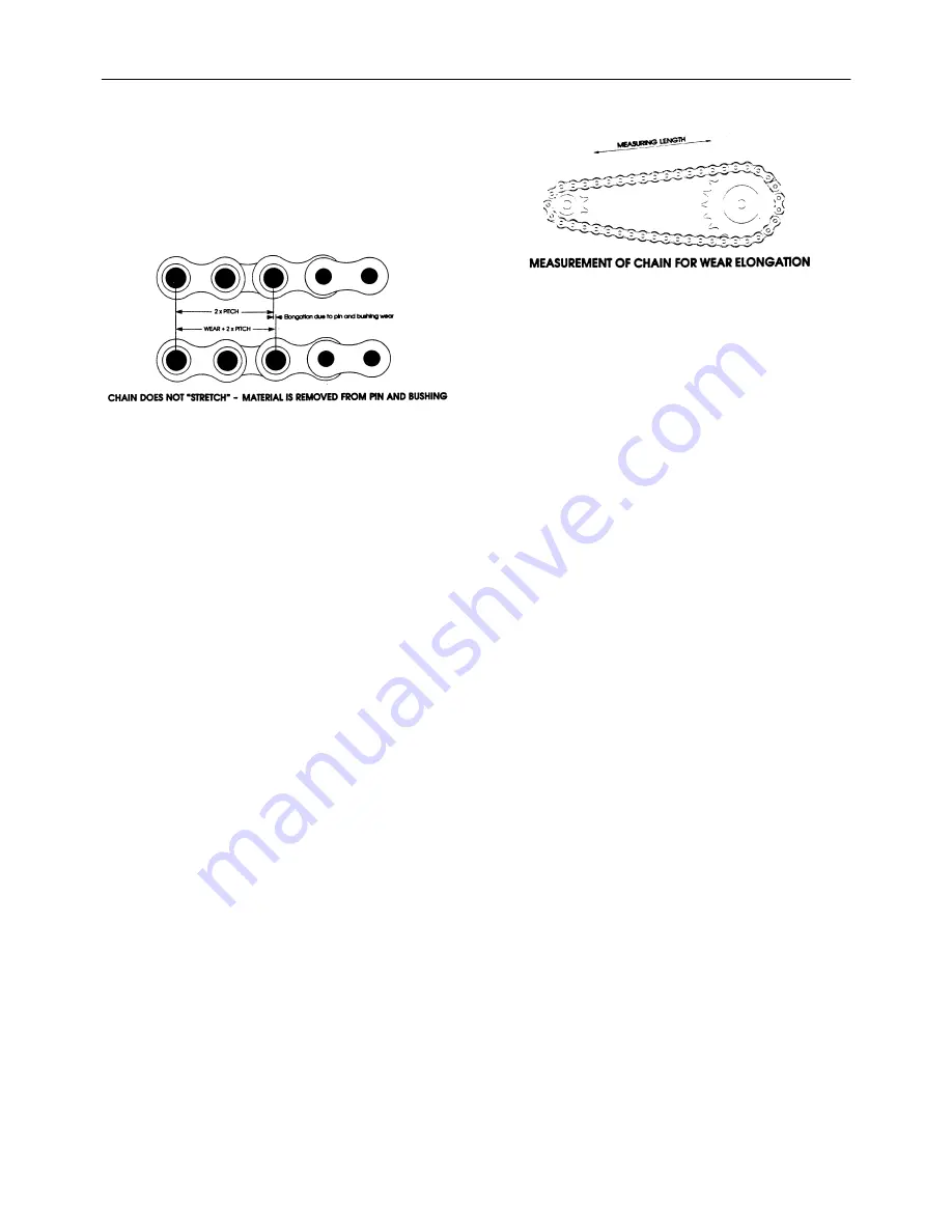
ROLLER CHAINS
Chain Wear
The individual joints in a roller chain articulate as they
enter and leave the sprockets. This articulation re-
sults in wear on the pins and bushings. As material
is worn away from these surfaces the chain will grad-
ually elongate.
Elongation is normal and may be minimized by prop-
er lubrication and drive maintenance. The rate of
wear is dependent upon: the relationship between
the load and the amount of bearing area between pin
and bushing, the material and surface condition of
the bearing surfaces, the adequacy of lubrication,
and the frequency and degree of articulation be-
tween pins and bushings. The latter is determined by
the quantity of sprockets in the drive, their speeds,
the number of teeth and the length of the chain in
pitches.
Relatively accurate wear measurements can be
made by using the above illustration. Measure as
closely as possible from the center of one pin to the
center of another. The more pitches (pins) contained
within the measurement increase the accuracy. If the
measured value exceeds the nominal by more than
the allowable percentage the chain should be re-
placed. The maximum allowable wear elongation is
approximately 3% for most industrial applications,
based upon sprocket design. The allowable chain
wear in percent can be calculated using the relation-
ship: 200/
N
, where
N
is the number of teeth in the
large sprocket. This relationship is often useful since
the normal maximum allowable chain wear elonga-
tion of 3% is valid only up to 67 teeth in the large
sprocket. In drives having fixed center distances,
chains running in parallel or where smoother opera-
tion is required, wear should be limited to approxi-
mately 1.5%.
For example, if 12 pitches (12 pins) of a #80 chain
were measured and the result was 12.360 or greater
(using 3% as the maximum allowable wear), the
chain should be replaced. Anything less than 12.360
would still be acceptable by most industrial stan-
dards.
Summary of Contents for RBX443
Page 1: ...5 5RXQG DOHU 5HSDLU 0DQXDO...
Page 12: ......
Page 42: ...SECTION 00 GENERAL INFORMATION CHAPTER 1 00 30...
Page 60: ...SECTION 31 IMPLEMENT DRIVELINE CHAPTER 1 31 18...
Page 82: ...SECTION 31 IMPLEMENT DRIVELINE CHAPTER 2 31 22...
Page 90: ...SECTION 35 HYDRAULIC SYSTEM CHAPTER 1 35 8...
Page 100: ...SECTION 55 ELECTRICAL SYSTEMS CHAPTER 1 55 10...
Page 113: ...SECTION 55 ELECTRICAL SYSTEMS CHAPTER 3 55 9 BALER LIGHTS WIRING DIAGRAM 17...
Page 114: ...SECTION 55 ELECTRICAL SYSTEMS CHAPTER 3 55 10...
Page 124: ...SECTION 62 PRESSING CHAPTER 1 62 2 SECTIONAL VIEWS FLOOR ROLL 1...
Page 128: ...SECTION 62 PRESSING CHAPTER 1 62 6...
Page 130: ...SECTION 62 PRESSING CHAPTER 2 62 2 SECTIONAL VIEWS STARTER ROLL 1...
Page 134: ...SECTION 62 PRESSING CHAPTER 2 62 6...
Page 150: ...SECTION 62 PRESSING CHAPTER 3 62 16...
Page 164: ...SECTION 62 PRESSING CHAPTER 4 62 14...
Page 178: ...SECTION 62 PRESSING CHAPTER 5 62 14...
Page 196: ......


