


99
VFD2 Acceleration Time (ACCL)
This configuration sets the acceleration time from zero to max-
imum output frequency. Power to the VFD must be cycled in
order for a change to this configuration to take effect.
VFD2 Deceleration Time (DECL)
This configuration sets the deceleration time from maximum
output frequency to zero. Power to the VFD must be cycled in
order for a change to this configuration to take effect.
VFD2 Switching Frequency (SW.FQ)
This configuration sets the switching frequency for the drive.
Power to the VFD must be cycled in order for a change to this
configuration to take effect.
VFD2 Type (TYPE)
This configuration sets the type of VFD communication. This
configuration should not be changed without first consulting a
Carrier service engineering representative.
Remote Control Switch Input
The remote switch input is located on the RXB board and con-
nected to TB201 terminals 3 and 4. The switch can be used for
several remote control functions. See Table 81.
Table 81 — Remote Switch Configuration
Remote Input State (Inputs
GEN.I
REMT)
This is the actual real time state of the remote input.
Remote Switch Config (Configuration
UNIT
RM.CF)
This is the configuration that allows the user to assign different
types of functionality to the remote discrete input.
• 0 — NO REMOTE SW — Remote switch will not be used.
• 1 — OCC-UNOCC SW — The remote switch input will con-
trol the occupancy state. When the remote switch input is ON,
the unit is forced into the occupied mode. When the remote
switch is OFF, the unit is forced into the unoccupied mode.
• 2 — STRT/STOP — The remote switch input will start
and stop the unit. When the unit is commanded to stop, any
timeguards in place on compressors will be honored first.
When the remote switch is ON, the unit will be command-
ed to stop. When the remote switch is OFF, the unit will be
enabled to operate.
• 3 — OVERRIDE SW — The remote switch can be used to
override any internal or external time schedule being used
by the control and force the unit into an occupied mode
when the remote input state is ON. When the remote
switch is ON, the unit will be forced into an occupied state.
When the remote switch is OFF, the unit will use its inter-
nal or external time schedules.
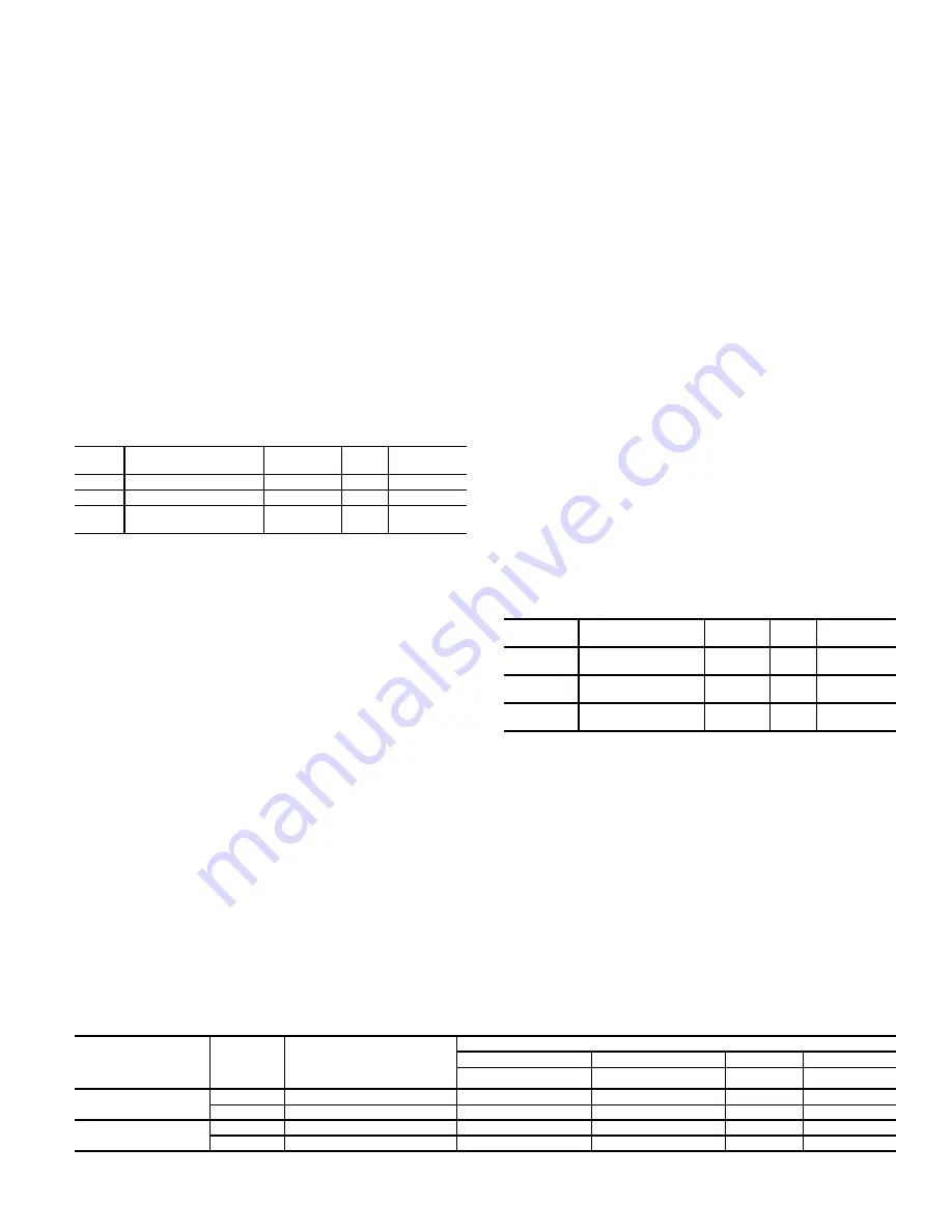
Remote Switch Logic Configuration (Configuration
SW.LG
RMI.L)
The control allows for the configuration of a normally open/
closed status of the remote input switch via RMI.L. If this
variable is configured OPEN, then when the switch is open,
the remote input switch perceives the logic state as OFF. Cor-
respondingly, if RMI.L is set to CLOSED, the remote input
switch will perceive a closed switch as meaning OFF. See
Table 82.
Hot Gas Bypass
The
Comfort
Link control system supports the use of an option-
al minimum load hot gas bypass valve (MLV) that is directly
controlled by the
Comfort
Link control system. This provides
an additional stage of capacity as well as low load coil freeze
protection. Hot gas bypass is an active part of the P-Series
Comfort
Link capacity staging and minimum evaporator load
protection functions. It is controlled through the Minimum
Load Valve function. The hot gas bypass option consists of a
solenoid valve with a fixed orifice sized to provide a nominal
3-ton evaporator load bypass. A hot gas refrigerant line routes
the bypassed hot gas from the discharge line of circuit A to the
suction line of circuit A. An additional thermistor in the suc-
tion line allows the unit control to monitor suction superheat.
When the unit control calls for hot gas bypass, the hot gas by-
passes the evaporator and adds refrigeration load to the com-
pressor circuit to reduce the cooling effect from Circuit A.
The hot gas bypass system is a factory-installed option in-
stalled on Circuit A only. This function is enabled at
Configu-
ration
COOL
MLV
. When this function is enabled, an ad-
ditional stage of cooling capacity is provided by the unit con-
trol staging sequences (see Appendix C).
Space Temperature Offset
Space Temperature Offset corresponds to a slider on a T56 sen-
sor that allows the occupant to adjust the space temperature by
a configured range during an occupied period. This sensor is
only applicable to units that are configured as Multi-Stage SPT
control (
Configuration
UNIT
C.TYP
= 4).
Space Temperature Offset Sensor (Configuration
UNIT
SENS
SP.O.S)
This configuration disables the reading of the offset slider.
Space Temperature Offset Range (Configuration
UNIT
SENS
SP.O.R)
This configuration establishes the range, in degrees F, that the
T56 slider can affect
SPTO
when adjusting the slider from the
far left (
-
SP.O.R
) to the far right (+
SP.O.R
). The default is 5°F.
Space Temperature Offset Value (Temperatures
AIR.T
SPTO)
The Space Temperature Offset Value is the reading of the slider
potentiometer in the T56 that is resolved to delta degrees based
on
SP.O.R
.
Table 82 — Remote Switch Logic Configuration
ITEM
EXPANSION
RANGE
UNITS
CCN
POINT
REMT
Remote Input State
ON/OFF
RMTIN
RM.CF
Remote Switch Config
0 to 3
RMTINCFG
RMI.L
RemSw
Off-Unoc-Strt-NoOv
Open/Close
RMTINLOG
ITEM
EXPANSION
RANGE
UNITS
CCN
POINT
SP.O.S
Space Temp
Offset Sensor
Enable/
Disable
SPTOSENS
SP.O.R
Space Temp
Offset Range
1 to 10
SPTO_RNG
SPTO
Space Temperature
Offset
+-
S
P.O.R
^F
SPTO
REMOTE
SWITCH LOGIC
CONFIGURATION
(RMI.L)
SWITCH
STATUS
REMOTE INPUT STATE
(REMT)
REMOTE SWITCH CONFIGURATION (RM.CF)
0
1
2
3
No Remote Switch
Occ-Unocc Switch
Start/Stop
Override
OPEN
OPEN
OFF (0)
xxxxx
Unoccupied
Start
No Override
CLOSED
ON (1)
xxxxx
Occupied
Stop
Override
CLOSED
OPEN
ON (0)
xxxxx
Occupied
Stop
Override
CLOSED
OFF (1)
xxxxx
Unoccupied
Start
No Override
Summary of Contents for Weathermaster 48P2030-100
Page 130: ...130 Fig 19 Typical Power Schematic Sizes 040 075 Shown ...
Page 131: ...131 Fig 20 Main Base Board Input Output Connections ...
Page 132: ...132 Fig 21 RXB EXB CEM SCB Input Output Connections ...
Page 133: ...133 Fig 22 Typical Gas Heat Unit Control Wiring 48P030 100 Units Shown ...
Page 134: ...134 Fig 23 Typical Electric Heat Wiring 50P030 100 Units Shown ...
Page 135: ...135 Fig 24 Typical Power Wiring 115 V ...
Page 136: ...136 Fig 25 Typical Gas Heat Section Size 030 050 Units Shown ...
Page 138: ...138 Fig 27 Component Arrangement Size 030 035 Units ...
Page 139: ...139 Fig 28 Component Arrangement Size 040 075 Units ...
Page 140: ...140 Fig 29 Component Arrangement Size 090 100 Units ...


