COPYRIGHT © 2006 CANON ELECTRONICS INC. CANON DR-1210C FIRST EDITION FEB. 2006
2-11
CHAPTER 2 FUNCTION & OPERATION
IV. CONTROL SYSTEM
1. Control Block Diagram
The main PCB controls this machine.
However, it has no firmware. The low level
driver (LLD), which is installed on the com-
puter in conjunction with the driver, has the
functions as a firmware. When the scanning
start command is executed, the scanning
conditions are written on the memory for
controller (IC1) on the main PCB.
In addition, the operation panel is
equipped with an operation PCB for the
operation buttons and a liquid-crystal mod-
ule (LCM) for display.
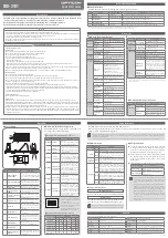
The figure below shows a control block
diagram of the main PCB and the functions
of major ICs.
Motor
driver
Motor
driver
DC/DC
converter
(IC2/IC4/IC6)
Regulator
(IC3/IC5)
(IC8)
Controller
(IC1)
SDRAM
(IC7)
Flash
ROM
X'tal
24V
(IC13)
(IC12)
Power
switch
AC adapter
USB
Feeder
Scanner
motor
Operation
panel
12MHz
(IC14)
Reading
unit
Analog
processor
Main PCB
Figure 2-401