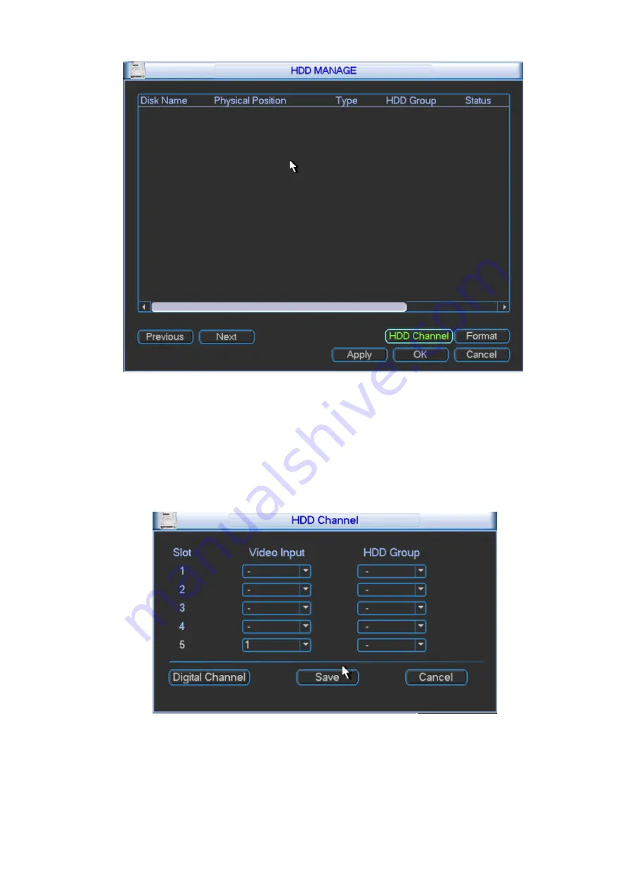
Burg Wächter KSC-USB-NET User Manual Download Page 80


74 


Figure 3- 66 

Type: write-read disk and read-only disk.  
HDD: Set current port input remote storage directory or external HDD no.  
Channel  
HDD channel: You can set HDD channel according to your actual condition. Slot sets local video 
input. Digital channel sets remote video input. 
Please see Figure 3- 67. 


Figure 3- 67 

Format: Format disk, clear data.  


3.2.5.2 

Abnormality 

Summary of Contents for KSC-USB-NET

Page 1: ...i Video Matrix Platform V 2 0 0 ...

Page 2: ...rm 4 CH HDMI Encoding Card 11 1 5 6 VEC0404HH Video Matrix Platform 4 CH HDMI Encoding Card 12 1 5 7 VDC0404D Video Matrix Platform 4 CH DVI Decoding Card 13 1 5 8 VDC0404V Video Matrix Platform 4 CH VGA Decoding Card 14 1 5 9 VDC0404H Video Matrix Platform 4 CH HDMI Decoding Card 14 1 5 10 VDC0404B Video Matrix Platform 4 CH CVBS Decoding Card 15 1 5 11 VDC0404S Video Matrix Platform 4 CH SDI Dec...

Page 3: ...utdown 85 4 WEB OPERATION 86 4 1 Network Connection 86 4 2 Login 86 4 3 Screen 87 4 3 1 Add TV Wall 88 4 3 2 Window 89 4 3 3 Signal Config 90 4 3 4 Scheme 91 4 3 5 Playback 94 4 3 6 Other Config and Operation 95 4 4 Preview 101 4 4 1 Window 102 4 4 2 Signal Config 102 4 4 3 PTZ Control 103 4 4 4 Playback 104 4 5 Setup 105 4 5 1 System Setup 105 4 5 2 Network Setup 116 4 5 3 Storage Management 123 ...

Page 4: ...iv 5 DSS OPERATION 169 6 FAQ 170 6 1 FAQ 170 6 2 Maintenance 173 APPENDIX A MOUSE CONTROL 174 ...

Page 5: ...urchasing our Video Matrix Platform system Here you can find information about features and functions as well as a detailed menu tree Before installation and operation please read the following safeguards and warnings carefully ...

Page 6: ...ts on the device 4 Qualified engineers needed All the examination and repair work should be done by the qualified service engineers We are not liable for any problems caused by unauthorized modifications or attempted repair 5 Environment The device should be installed in a cool dry place away from direct sunlight inflammable explosive substances and etc 6 Accessories Be sure to use all the accesso...

Page 7: ...sertion centralized management and distributed deployment It achieves switches among analog signal digital signal HD network signal and HD digital video signal and making HD image available on video walls It is a platform product integrating video signal encoding decoding centralized data storage online real time preview and various networks pre plan log user authority management device maintenanc...

Page 8: ...on standard support dual stream technology VBR support composite streaming and video streaming encode and during composite streaming A V sync A V encoding card may support 32 ch BNC CVBS signal 8 CH HD SDI 4 CH DVI support DVI VGA HDMI signal 8 ch HDCVI 4 ch VGA support DVI HDMI signal Max support 80 ch HD video encoding capacity or 320 ch SD video encoding capacity A V Decoding Output DVI HDMI ou...

Page 9: ...rebooting and remotely inputting outputting parameters Other Complete set of operation alarm abnormality and log recording simplifying user and technical Complete user authority management and storage management while the authority can be subdivided into a channel and a single HDD making the device more user friendly Support local and remote update guaranteeing update to catch changing market dema...

Page 10: ...MI decoding card 4 HDMI video output port Optional VDC0404B CVBS decoding card 4 BNC video output port 4 BNC audio output port Optional VDC0404S SDI decoding card 4 SDI video output port 4 BNC audio output port Optional 4 Platform Card BC9500 Platform card 1 4 RJ45 GB interface 2 optional TB fiber port 3 USB port 4 1 VGA port 5 1 HDMI port 6 1 standard RS232 port Optional 1 4 Host System 1 4 1 4U ...

Page 11: ...nction Card Function Card Control panel s rear slot marked as C Duel power module support 220V modules 1 4 2 Main Control Panel 1 4 2 1 Interface Introduction Please see Figure 1 3 Figure 1 3 No Interface Function 1 Reset Button 1 support restoring to default settings 2 Mainboard Power Indicator 1 display mainboard power status System Status Indicator 1 display system working status PCI E Status I...

Page 12: ...ntrol Panel 1 4 3 1 Interface Introduction Please see Figure 1 4 Figure 1 4 No Interface Function 1 Clear Alarm Button 1 support to clear alarm 2 Mainboard Power Indicator 1 display mainboard power status 3 Alarm Indicator 1 display alarm status 4 System Status Indicator 1 display system working status 5 RS232 1 DB9 debug serial or central control serial 6 RJ45 Port 3 for control of peripheral equ...

Page 13: ...Encoding Function Support DVI HD input port 1080P 60Hz 1680 1050 60Hz 1440 900 60Hz 1366 768 60Hz 1280 1024 60Hz 1280 960 60Hz 1280 800 60Hz 1280 720 60Hz 1152 864 60Hz 1024 768 60Hz 800 600 60Hz Adopt H 264 video compression technology Video encoding parameter is adjustable in each channel including resolution bit stream rate image quality and etc Each channel supports schedule and event as compr...

Page 14: ...port VGA signal input 2 buttons hot swap 4 indicators High speed connector including x4 PCI E gen2 12V DC power Encoding Function VGA HD input port UXGA 60Hz 1080P 60Hz 1080P 50Hz 720P 50Hz 720P 60Hz 1024x768 60Hz 1024x768 75Hz 1280x1024 60Hz 1280x1024 75Hz Adopts H 264 video compression technology Video encoding parameter is adjustable in each channel including resolution bit stream rate image qu...

Page 15: ...nd Performance Features 8 ch HD SDI video interface input 2 ch RS485 interface 2 buttons hot swap 4 indicators High speed connector including x8 PCI E gen2 12V DC power Encoding Function Adopts H 264 video compression technology Video encoding parameter is independently adjustable in each channel including resolution frame rate bit stream rate image quality and etc Each channel supports schedule a...

Page 16: ...t external and built in Countercharge 2 buttons hot swap 4 indicators High speed connector including x4 PCI E gen2 12V DC power Encoding Function HDCVI HD input port 1080P 30Hz 1080P 25Hz 720P 60Hz 720P 50Hz 720P 30Hz 720P 25Hz Adopts H 264 video compression technology Adopts G711a PCM and G711u audio compression standard Video encoding parameter is independently adjustable in each channel includi...

Page 17: ...5 1 Main Features and Performance Features 4 ch HDMI video input interface support DVI and HDMI signal input 2 buttons hot swap 4 indicators High speed connector including x4 PCI E gen2 12V DC power Encoding Function Video encoding parameter is independently adjustable in each channel including resolution frame rate bit stream rate image quality and etc Each channel supports schedule and event as ...

Page 18: ...nterface input 2 ch RS485 interface 2 buttons hot swap 2 indicators High speed connector including x4 PCI E gen2 12V DC power Encoding Function Video encoding parameter is independently adjustable in each channel including resolution frame rate bit stream rate image quality and etc Each channel supports schedule and event as compression parameters Support composite and bit stream encoding A V are ...

Page 19: ...h D1 or 16 ch 1080p decoding output Support 16 ch D1 uncompressed data output Support DVI output interface 1080p 50 60Hz 1280 720 50 60Hz 1024 768 60Hz Support hot swap 1 5 7 2 Interface Introduction VOUT video output port DVI port 1 5 7 3 Technical Specifications Model VDC0404D A V Output Video Output 4 ch DVI digital video port output A V Decoding Parameter Video Compression Standard H 264 MPEG4...

Page 20: ...upport hot swap 1 5 8 2 Interface Introduction VOUT video output port VGA port 1 5 8 3 Technical Specifications Model VDC0404V A V Output Video Output 4 ch VGA digital video port output A V Decoding Parameter Video Compression Standard H 264 MPEG4 Video Decoding Resolution 1920x1080 1280x1024 1280x720 1024x768 Video Processing Capacity Support 64 ch 4CIF 24 ch HD 720P 16 ch HD 1080P image decoding...

Page 21: ...andard H 264 MPEG4 Video Decoding Resolution 1080P SXGA WXGA Video Processing Capacity Support 64 ch 4CIF 24 ch HD 720P 16 ch HD 1080P image decoding output support 16 ch 4CIF or 8 ch HD original data stream direct output Bit stream Rate 3584Kbps 8192Kbps customizable max 8192 Kbps Image Display Method 1 4 8 9 16 screen split Audio Stream 32K 16bit 1 5 10 VDC0404B Video Matrix Platform 4 CH CVBS D...

Page 22: ...d 1 4 9 screen split 1 5 11 VDC0404S Video Matrix Platform 4 CH SDI Decoding Card Please see Figure 1 15 Figure 1 15 1 5 11 1 Main Features and Performance Features 4 ch SDI video interface output 4 ch BNC audio output 2 buttons hot swap 2 ch RS485 interface High speed connector including x4 PCI E gen2 12V DC power 1 5 11 2 Interface Introduction VOUT video output port HDMI port AOUT audio output ...

Page 23: ...Software platform management Single platform supports 700Mbps multi address mode GB environment 1500Mbps pure forward bound mode Device input capacity 500 devices 2000 channels Power indicator HDD indicator PCle indicator 1 5 12 2 Interface Introduction 4 RJ45 interface 10M 100M 1000M network TB fiber port optional 4 USB interface 1 VGA 1 HDMI 1 standard ES 232 interface 1 5 12 3 Technical Specifi...

Page 24: ...parts are included you may remove protector on device connection between mainboard and interface board is loose 2 2 Accompanied Assessory Bag please make sure all contents match the checklist 2 3 Device Installation At time of inserting mainboard and Function Card into chassis please remove the protection cover at connection interface of real panel Connect Ethernet port 2 on main control panel to ...

Page 25: ...ce 1 Enter main menu in shutdown system select shutdown device 2 Press ON button on panel for 5s to shutdown Note Method 1 is recommended Stop all performance of the device and then you may unplug the device from power supply 3 1 2 1 Outage Recovery When the device is under working status and there is an outage or forced shutdown the system can automatically save and resume previous working status...

Page 26: ...fault Password default hidden user You can use USB mouse front panel remote control or keyboard to input About input method Click to switch between numeral English character small capitalized and denotation and click designated buttons on soft keyboard with the mouse Note For security reason please modify password after you first login To add user group user and edit user please refer to User Acco...

Page 27: ...igure 3 2 3 1 4 Main Interface Introduction After you logged in you will enter main interface as shown in Figure 3 3 for various icon definitions please refer to the following Chart 3 1 Figure 3 3 1 2 3 4 5 ...

Page 28: ... to 8th channel and 9th to 16th channel Under 9 ch mode you may switch between 1st to 9th channel and 8th to 16th channel Under 16 ch mode you may view full 16 channels at the same time Independent display button It allows an independent view of any window selected in a single screen or independent view plus crossing screen function in a cubeless video wall To exit you need to re split and drag se...

Page 29: ...all output interface names under current output card You may switch display control area to current output interface by double clicking on output interface name to achieve control over displayed contents of current output interface 3 Cubeless video wall List Area Display current cubeless video wall list You may double click cubeless video wall to switch from display control area to current cubeles...

Page 30: ...24 3 1 6 Input Device Tree Introduction The input device tree is show as follows please see Figure 3 5 and Chart 3 3 Figure 3 5 1 2 3 4 5 ...

Page 31: ...ing input interface name you may switch from local input channel to currently selected input channel 3 Remote Input List Area Display added remote device list and devices may be DVR IPC and otherencoding devices It will display icon and you may click it to extend the list as Meanwhile channels supported by current remote device will be listed 4 Remote Input Channel List Area Display all input chan...

Page 32: ...el the status info is blank You may click this channel to view it and its corresponding area will turn yellow 2 Remote Input Display ce channel then device ID IP address device type channel name manufacturing protocol will be displayed When you click this channel you will see icon which allow you to close displayed contents in this channel 3 Local Input Display name slot channel will be displayed ...

Page 33: ...27 Figure 3 8 In display window select corresponding channel and then its corresponding window turns yellow Please see Figure 3 8 ...

Page 34: ...28 Figure 3 9 Switch to input device list Please see Figure 3 9 ...

Page 35: ...29 Figure 3 10 Double click corresponding input channel and then you may config video to output interface Please see Figure 3 10 Double click homepage you will see Figure 3 11 ...

Page 36: ...t screen When signal of input is more than the max split of output screen auto tour starts Scheme Config scheme Save all output screen config of current device Main Menu Display main menu Shutdown Shutdown device The following sections are descriptions of input group and scheme For other functions please refer to later chapters 3 1 9 Input Group Step 1 Click input group and you will enter Figure 3...

Page 37: ...31 Figure 3 12 Step 2 Click add You will see Figure 3 13 Figure 3 13 ...

Page 38: ...32 Step 3 Select input source means selected Click add and fill in name of input group Click OK See Figure 3 15 and Figure 3 16 Figure 3 14 ...

Page 39: ...ue adding if you need If you want to delete input group you can check the small box in front of designated group and click delete Click OK to confirm When you are done click OK to exit You can open the input group you added in Figure 3 17 ...

Page 40: ...34 Figure 3 16 Step 5 In output device list double click output channel name and select one output channel You will see its corresponding window turns yellow Please see Figure 3 17 ...

Page 41: ...35 Figure 3 17 Step 6 Switch to input device list Double click configured input group you will see configured signal source appear on output channel See Figure 3 19 ...

Page 42: ...36 Figure 3 18 Note When signal of input is more than the max split of output screen auto tour starts 3 1 10 Scheme Step 1 Click scheme and you will enter Figure 3 19 ...

Page 43: ...37 Figure 3 19 Step 2 Click add to add new scheme See Figure 3 20 Figure 3 20 Step 3 If the name has already existed you may rename it See Figure 3 21 ...

Page 44: ...rt end time and etc BPS used capacity per hour Log It displays system log for important event You may appoint log for event requires recording Version It displays system hardware features software version release date and etc Online User To view online user info Status To view fan speed card information and its temperature info source info net percentage CPU percentage and memory percentage Settin...

Page 45: ...gement emptying HDD and etc Note If you edit HDD property then you must reboot the system to make change effective Abnormality To set up alarm for abnomaly event such as no HDD HDD error Record To boot up or shutdown channel schedule Account To modify user group and user account Auto Maintain To set up auto maintenance for item requires it Cubeless video Wall To config cubeless video wall output R...

Page 46: ... 3 2 3 Info After you enter information menu the submenu is shown as below Please see Figure 3 23 There are total five icons HDD info bit per second BPS log version online user and status Figure 3 23 3 2 3 1 HDD Info ...

Page 47: ...system booted up if there is any conflict system goes to HDD information interface directly Please note system does not ask you to deal with it forcedly When HDD confliction occurs you can check whether system time and HDD time are identical or not If they are not identical please go to General to adjust system time or go to HDD Management to format HDD and then reboot device Please see Figure 3 2...

Page 48: ...rface displays system log file Log types include system config storage alarm record account clear and playback Pleased select start time and end time then click search button You can view the log files in list format System max displays 15 logs in one page Please use page up down button to turn pages Please see Figure 3 26 ...

Page 49: ...43 Figure 3 26 3 2 3 3 BPS This interface real time displays bit stream Kb S and used space MB H while wave pattern better shows changes in bit stream Please see Figure 3 27 Figure 3 27 ...

Page 50: ...a USB device to device Note The upgrading file in USB must be named update bin 3 2 3 5 Online Users In this interface you can view and management online users connected to device You may also disconnect or shield selected with users for a set period up to 65535s Please see Figure 3 28 Figure 3 28 3 2 3 6 Status Please see Figure 3 29 ...

Page 51: ...rrent temperature and status of each card Source Information It displays usage of two group of power Time It displays current time Net percentage It displays net sending and receiving percentage of each network port CPU percentage It displays usage percentage of each CPU Memory percentage It displays percentage of memory 3 2 4 System Setting System setting includes submenu general encode schedule ...

Page 52: ...46 Figure 3 30 Note Only authorized user can enter system setting 3 2 4 1 General General setting interface is shown as follow please see Figure 3 31 Figure 3 31 ...

Page 53: ... Device ID You may edit device ID value is 120 minutes Auto logout You may set standby interval which is a specified period of time between the moment once login user becomes inactive and the auto logoff of this user It ranges from 0 to 60 minutes 0 is log off immediately once this use becomes inactive Users are required to log in again for operations in this case Interval To set interval between ...

Page 54: ...pports various resolutions you can select from the dropdown list The standard definition main stream supports D1 HD1 2CIF CIF QCIF and the high definition main stream supports 1080P 720P D1 and etc Please note the option may vary due to different series Frame rate Pal standard 1 frame s 25 frame s NTSC standard 1 frame s 30 frame s Bit rate type System supports two types CBR and VBR You cannot set...

Page 55: ...Preview means the cover area cannot be viewed by user when system is in preview status Monitor Monitor means the cover area cannot be view by the user when system is in monitoring status Time display You can select whether system displays time or not in decoding data for playback Please set button and then drag the title to the corresponding position in the screen Channel display You can select wh...

Page 56: ...ithin this time period You may set by day of week while each day has setting in six periods You can Pre record System can pre record the video before the event occurs into the file The value ranges from 0 to 30 seconds depending on the bit stream Note Pre record time depends on its bit stream as pre record time may not be reached in case of large bit stream Record types There are three types regul...

Page 57: ...ng to another After setting in channel 1 you can click copy button and turn to channel 3 and then click paste button or vice versa 2 You can finish setting for one channel and then click save button or you can finish all setting and then click save button to memorize all the settings 3 2 4 4 RS232 RS232 interface is shown below as in Figure 3 38 ...

Page 58: ...ecial keyboard to control the device MatrixCom is to connect to the peripheral matrix control PELCO is for you to control matrix via PELCO Baud rate You can select proper baud rate Data bit You can select proper data bit The value ranges from 5 to 8 Stop bit There are two values 1 2 Parity there are four choices odd even space mark System default setting is Function Console Baud rate 115200 Data b...

Page 59: ... from 1 2 Default Ethernet port You can select from 1 2 Under multiple addresses and bridge mode only Aggregation strategy Under aggregation link mode only Strategies available are MAC address based IP address and port based IP address and MAC address based IP address and port based IP version IPv4 and IPv6 IP address Here you can input IP address and then set corresponding subnet mask and default...

Page 60: ...P address Alternate DNS server Set DNS server alternate IP address Transfer mode Here you can select the priority among fluency video qualities self adaption LAN download Under sufficient bandwidth system can process the downloaded data first if you enable this function The download speed is 1 5X or 2 0X of the normal speed LAN service Click to enter LAN service setting as shown in Figure 3 40 Fig...

Page 61: ...tting interface is shown as in Figure 3 42 Host IP Input your PC address where SNTP server is installed Port This SNTP supports TCP transmission only Port default value is 123 Time zone select your corresponding time zone here Here is a sheet for your time zone setting City Region Name Time Zone London GMT 0 Berlin GMT 1 Cairo GMT 2 Moscow GMT 3 ...

Page 62: ...st address and add ins group Open preview to monitor via multicast 3 2 4 5 4 DDNS DDNS setting interface is shown as in Figure 3 43 Figure 3 43 You need a PC of fixed IP in the internet and there is the DDNS software running on this PC In other words this PC is a DNS domain name server In network DDNS please select DDNS type currently support CN99 DDNS NO IP DDNS Private DDNS and Dyndns DDNS which...

Page 63: ...n of the device Status Display UPNP function status including success fail and searching Router LAN IP It is the router IP in the LAN WAN IP It is the router IP in the WAN PAT table Display info of added ports You may add new port and delete existing port Note Double clicke item you can change the corresponding mapping information Please see Figure 3 45 Figure 3 45 3 2 4 5 6 Email ...

Page 64: ...ect or the Abnormality event activates the email system sends out the email according to the interval you specified here This function is very useful when there are too many emails activated by the Abnormality events which may result in heavy load for the email server Health email enable Please check the box here to enable this function This function allows the system to send out the test email to...

Page 65: ...3 47 Figure 3 47 3 2 4 5 8 iSCSI 1 Click system setting network network service setting iSCSI setting Set its parameter including host IP port 2 Click storage path setting 3 Select corresponding remote directory and then click OK to enable 4 Input correct username and password Click Add 5 Click OK Please see Figure 3 48 as guide ...

Page 66: ...enu system settings detect 2 There are no settings of detection area sensitivity or anti dither in video loss and camera mask 3 You can drag your mouse to set motion detect area You may right click to save your selection and exit setting Please click save before you exit ...

Page 67: ...wn list you can select motion detect type Slot select slot to set Channel select the channel to activate motion detect or select all to include all channels under selected slot Region Move cursor to set and click enter The interface is shown as in Figure 3 50 The green zone is current cursor position Grey zone is the motion detect zone Black zone is the disarmed zone Do remember click save button ...

Page 68: ...nt box to activate corresponding period Select all if you want set all periods at once Besides the above method you also may set period by week day and week end Week day and weekend setting 1 From the dropdown list you can select week day or weekend and then click the set button at the right You will see setting for you to define your week day and weekend For example you may set Monday to Friday a...

Page 69: ...0 Show message System can pop up a message to alarm you in the local host screen if you enabled this function Alarm upload System can upload the alarm signal to the network including alarm centre if you enabled this function Send email System can send out email to alert you when alarm occurs Record channel Select designated record channel same channel can be selected more than once When alarm occu...

Page 70: ...64 Figure 3 54 Buzzer Buzzer rings when motion detection alarms 3 2 4 6 2 Video Loss ...

Page 71: ...eo loss from the type list This function allows you to be informed when video loss occurred You can enable alarm upload send email and screen prompt function Note You can refer to setting in motion detect 3 2 4 6 3 Camera Masking Figure 3 56 ...

Page 72: ...face your default operation will not affect detection settings other than camera masking Note In motion detect settings copy paste function is not valid for area parameters since video content in each channel are different 3 2 4 7 PTZ Step 1 PTZ and speed dome connection is right Speed dome address setting is right Step 2 Speed dome A and B line connect properly with A and B line Step 3 In the mai...

Page 73: ...t is fiber encoding card and HDCVI encoding card you can set countercharge front end function See Figure 3 58 Figure 3 58 After above setting is complete as may countercharge front end via video line please refer to RS 485 control 3 2 4 8 Display ...

Page 74: ...68 Display is shown below as in Figure 3 59 Figure 3 60 and Figure 3 61 Figure 3 59 ...

Page 75: ...69 Figure 3 60 ...

Page 76: ...70 Figure 3 61 Channel output name Click channel output name to enter channel name interface where you may edit channel name support maximal 20 characters which may vary among versions ...

Page 77: ...71 Figure 3 62 Color setting Click to enter image color output setting Please see Figure 3 62 Decoder screen setting Click to enter setting of decoder screen Please see Figure 3 63 Figure 3 63 ...

Page 78: ...settings please click save button system goes back to the previous menu Note System menu color language video standard IP address user account will not maintain previous setting after default operation 3 2 5 Advanced Double click advanced icon in the main window the interface is shown below as in Figure 3 65 There are total six function keys HDD manage abnormality record account auto maintain cube...

Page 79: ...then click HDD manage Please see Figure 3 66 You can see current HDD name type status free capacity and total capacity Operation include modify HDD property change to read write disk read only disk and clear disk You must save your changes and reboot device before updated changes come effective When HDD has error you may recover HDD ...

Page 80: ...put remote storage directory or external HDD no Channel HDD channel You can set HDD channel according to your actual condition Slot sets local video input Digital channel sets remote video input Please see Figure 3 67 Figure 3 67 Format Format disk clear data 3 2 5 2 Abnormality ...

Page 81: ...hannel s Latch Alarm latches one period and stops Unit is second with range between 10 and 300 Show message system can pop up the message in the local screen to alert you when alarm occurs Alarm upload System can upload the alarm signal to the network including alarm centre if you enabled current function Send email System can send out email to alert you when alarm occurs Buzzer Highlight the icon...

Page 82: ...o implement account management Please see Figure 3 70 For account management please note For the user account name and the user group the string max length is 6 byte The backspace in front of or at the back of the string is invalid There can be backspace in the ...

Page 83: ...admin and user One user should belong to one group User right cannot exceed group right Figure 3 71 Password Change Please select the account from the dropdown list input the old password and then input the new password twice Click the Save button to confirm current modification The password max length is 6 byte and first byte cannot be empty Please see Figure 3 71 For the users of user account ri...

Page 84: ...73 Add user interface is shown above as in Figure 3 73 he first three users have passwords same as the usernames respectively Except user 6666 other users rights such as monitor for this user so that you can view some channel view without login After you enter add user interface please input the user name password and select the group it belongs to from the dropdown list You may select same user m...

Page 85: ...fied time You can set to delete files or expired files for the specified days You can select proper setting from dropdown list Please see Figure 3 74 After all the settings please click save button system goes back to the previous menu 3 2 5 6 Cubeless Video Wall Here you can set cubeless video wall function Please see Figure 3 75 Figure 3 75 ...

Page 86: ... video wall Column Set number of columns of the cubeless video wall Windows Rank all splicing units Output screen Output channel of each splicing unit For example the cubeless video wall is 2 2 as in Figure 3 77 Figure 3 77 Step 1 Set name row and column of the cubeless video wall Select output screen and click apply You must click apply every time you select output screen Click OK You will see Fi...

Page 87: ...d ones Select cubeless video wall and click remove to delete it Step 3 You can edit name of cubeless video wall as in Figure 3 79 Figure 3 79 Step 4 Click OK Step 5 Click OK to see the configured cubeless video wall You can find it in output list 3 2 5 7 Raid Config Raid for record storage ...

Page 88: ...82 Figure 3 80 Click Add to add new Raid Select corresponding level Figure 3 81 ...

Page 89: ...or IPC 3 2 6 1 IP Search 1 In remote device interface click IP search You may search all remote devices in network The display includes IP address port manufacturer protocol and type please see Figure 3 83 2 Check box in front of remote device you want to add Multiple selections is allowed 3 Click add to add device 4 Click OK to complete operation ...

Page 90: ... click manually add A prompt pops up and you need to input device name manufacturer IP address TCP port username password and channel number Please see Figure 3 84 2 Make sure you save changes 3 Add device into added device 4 Click OKto complete operation ...

Page 91: ...x for you to select Please see Figure 3 85 Logout menu user log out menu You need to input password when you login the next time Restart application reboot Shutdown system shuts down and turns off power Switch user you can use another account to log in Shutdown menu includes the above four functions ...

Page 92: ...r prompt ActiveX and plug in IE7 and IE8 are preferred Step 5 Open the IE and then input IP address Step 6 It pops up security box asking you whether you accept webrec cab control unit please select and system will start to install If system forbid this download please check if there is other plug in blocking the download and meantime lower IE browser security level 4 2 Login Figure 4 1 Step 1 Ope...

Page 93: ...87 Figure 4 2 Step 4 Click OK See Figure 4 3 Figure 4 3 Step 5 Follow system instructions to install or load control unit Note Click Logout to exit Select Screen tab see Figure 4 4 ...

Page 94: ...88 Figure 4 4 4 3 1 Add TV Wall For first time login user you shall add TV wall see Figure 4 5 Figure 4 5 ...

Page 95: ...e current window moves following mouse movement release mouse move window to target position Click the window at any one of control point to adjust window size 4 3 2 2 Adjust Window There are window adjustment bar in the upper right see Figure 4 7 Figure 4 7 1 Start Stop Signal Tour See Ch 4 3 3 4 2 Split Split window you can select 2 split horizontal vertical 4 split 9 split 16 split Note When wi...

Page 96: ...rce config steps in Ch 4 5 5 2 Network signal show added device signal source in remote device click to add See Ch 4 5 5 1 4 3 3 2 Signal Group It shows added group and signal source in group added in signal group See Ch 4 5 5 3 4 3 3 3 Signal on Wall Step 1 Select one window on video wall or click left key of mouse to draw box on TV wall Step 2 In Device Tree or Signal Group select signal source ...

Page 97: ...eam type Note Click of a certain signal so this signal will not be shown in tour list but stil exists in signal groupl Set validity time Click in the upper right corner stop signal tour 4 3 4 Scheme Scheme is plan of TV wall including current split mode video source info tour setup of TV wall 4 3 4 1 Add Scheme Step 1 Customize window layout on screen Step 2 Click See Figure 4 10 Figure 4 10 Step ...

Page 98: ...fully added scheme you can select scheme in Homepage 4 3 4 2 Scheme Setup Click see Figure 4 11 Figure 4 11 4 3 4 2 1 Management Click to rename scheme see Figure 4 12 Figure 4 12 Click to delete scheme 4 3 4 2 2 Tour ...

Page 99: ...terval and scheme name click Note Click of scheme to adjust sequence Step 3 Click Save Set to ON See Figure 4 14 Figure 4 14 4 3 4 2 3 Switch After you set switch time for a scheme you can switch time system auto switched to this scheme Step 1 Select Switch tab see Figure 4 15 ...

Page 100: ...94 Figure 4 15 Step 2 Select scheme week and set switch time Note Check time to enable it Time of two schemes cannot be the same Step 3 Click OK 4 3 5 Playback Select Playback tab see Figure 4 16 ...

Page 101: ...ag mouse to zoom in out 5 Calendar Under any play mode click calendar you want to view record pattern of this day will be auto shown on time axis Blue means there is record picture on that day No color means there is no record picture on that day 6 Stream Type Select playback steam type 4 3 6 Other Config and Operation 4 3 6 1 Auto Alignment Click all windows will auto align in the following metho...

Page 102: ...in the same size Window sequence is from top to bottom horizontally 4 3 6 2 Split Window Select window you want to split click see Figure 4 18 Figure 4 18 You can manually enter split number i e 3 3 and click OK 4 3 6 3 Refresh TV Wall Click to refresh TV wall 4 3 6 4 Clear TV Wall ...

Page 103: ...click On or Off Check All if you want to select all screens 4 3 6 6 PTZ Control It supports PTZ control for camera with speed dome Note Before you can use PTZ control you must set according to instructions in Ch 4 5 1 8 and wiring must all be correct Select window unit where signal locates click see Figure 4 20 ...

Page 104: ...98 Figure 4 20 4 3 6 7 Virtual LED You can add title overlay on screen via virtual LED Step 1 Click See Figure 4 21 Figure 4 21 Step 2 Click See Figure 4 22 ...

Page 105: ...99 Figure 4 22 Step 3 Set title content font and etc Step 4 Click OK See Figure 4 23 Figure 4 23 4 3 6 8 Background You can set background Note You must upload picture first see Ch 4 5 1 6 ...

Page 106: ...4 3 6 9 Decoding Strategy Select network signal window other signals are not supported click let user decide between fluency and real timeness Figure 4 25 4 3 6 10 Small Map Click see Figure 4 26 Figure 4 26 Drag mouse or scroll mouse to adjust area zone the window will zoom in out in video ...

Page 107: ...er cannot operate this TV wall Select Preview tab see Figure 4 27 Figure 4 27 1 Window Preview window video see Ch 4 4 2 2 Window Split Support 4 9 16 25 and 36 splits 3 Talk Click this icon to enable talk 4 Signal Config Playback Control Can config signal or open playback see Ch 4 4 3 and 4 4 5 5 PTZ Control Operate PTZ camera see Ch 4 4 4 ...

Page 108: ... in out 2 Local Record Click this icon to record video see Ch 4 5 1 10 3 Snapshot Click this icon to snapshot see Ch 4 5 1 10 4 Audio ON Click this icon to enable audio of video 5 Close Close the window 4 4 2 Signal Config You can directly select signal or enter signal name to search signal 4 4 2 1 Device Tree In device tree to show all signal sources Local signal show local signal source see Ch 4...

Page 109: ...rol It supports camera with PTZ Note Before you can use local serial PTZ control you shall set corresponding setup and ensure wirings all are correct See Ch 4 5 1 8 See Figure 4 29 Figure 4 29 Parameter Note Scan Click Setup rotate camera with direction keys and click set left border and set right border to set border of PTZ Click Start PTZ starts to scan click Stop to stop scanning Preset In fiel...

Page 110: ...th Pattern Enter pattern path click Start to start pattern click Stop to stop pattern Click Add to set a new pattern path with start and end record Pan Click Start to pan click Stop to stop pan Lamp Wiper Click Open to enable lamp click Disable to turn off wiper See Ch 4 3 6 6 4 4 4 Playback See Figure 4 30 Figure 4 30 See Ch 4 3 5 Select date with record click to show record in list of that day s...

Page 111: ...1 System Setup You can set general user backup maintenance upgrade picture management fan control PTZ serial and storage path 4 5 1 1 General 4 5 1 1 1 Set General Info Step 1 Select Setup System Setup General General see ...

Page 112: ...evice language HDD Full Set HDD processing overwrite or stop Record Length Set record length as 0 min 120 min default is 60 Extract Frame Check box system will extract sub stream 2 in network channel and show it in channel list Step 3 Click OK 4 5 1 1 2 Set Date Step 1 Select Setup System Setup General Date see Figure 4 33 ...

Page 113: ... Check box to enable auto sync time DST Check box to enable DST DST Type Select DST by date or week Start Time End Time DST type select date enter year month day start time and end time DST type select week in dropdown list select month week start time and end time NTP Setup Check box enable NTP sync Time Zone Select time zone Server Enter server address or domain name Port Enter NTP server port n...

Page 114: ...group is 18 to 8 by default User group is ranked by user group or user level Group name cannot be repeated and one user belongs to one group only Currently logged in user cannot modify his her own right There is one default user admin as the highest right user 4 5 1 2 1 User Select Setup System Setup User Management User Management User you add delete and modify user password See Figure 4 34 Figur...

Page 115: ...is her user right must be within sub set of this group cannot be beyond group right range We recommend you to set general user right lower then high level user Step 3 In right list check right you want to add Check box to enable this right Check all box to select all Step 4 Click OK Modify User Step 1 Click of user See Figure 4 36 ...

Page 116: ... OK Modify Password Step 1 Check Modify Password box Step 2 Enter old password and enter new password confirm password Step 3 Click Save Delete User Click of user to delete user 4 5 1 2 2 Group In Setup System Setup User Management User Management Group you can add delete and modify group password ...

Page 117: ...e Ch 4 5 1 2 1 4 5 1 3 Backup Select Setup System Setup Backup see Figure 4 38 Figure 4 38 Click Import Config select backup file to import Click Export Config select storage path to export config file 4 5 1 4 System Maintenance Select Setup System Setup System Maintenance see Figure 4 39 ...

Page 118: ...efault the system will restore to default setup be careful 4 5 1 5 Upgrade Step 1 Select Setup System Setup System Upgrade see Figure 4 40 Step 2 Click Import select upgrade file Step 3 Click Upgrade to update and you will see progress bar 4 5 1 6 Picture After you upgrade background you can set background Step 1 Select Setup System Setup Picture Management see Figure 4 41 ...

Page 119: ... 3 6 8 4 5 1 7 Fan Control Select Setup System Setup Intelligent Temperature Control see Figure 4 42 Figure 4 42 There are three levels low speed medium speed and high speed different temperature range correspond to different speed 4 5 1 8 PTZ You need to set device protocol baud rate address parity to match camera protocol baud rate address parity in order to control PTZ Step 1 Select Setup Syste...

Page 120: ...re 4 43 Figure 4 44 Step 2 Set PTZ parameter Parameter Note Device Type Select device type Name Select analog matrix name Slot Select slot Channel Select channel Port Select port PTZ Type Only support local PTZ ...

Page 121: ...l You need to set data bit baud rate address to match device in order to connect the device Step 1 Select Setup System Setup Comm see Figure 4 45 Figure 4 45 Step 2 Set parameter Parameter Note Slot Select slot Channel Select channel COM Type Select com type Function Set function Data Bit Set data bit Stop Bit Set stop bit Baud Rate Set baud rate of device Parity Set device parity Address Set com ...

Page 122: ...tureDownload and C RecordDownload respectively 4 5 2 Network Setup 4 5 2 1 TCP IP You shall set device IP address and DNS server Note Make sure you have correctly connect into network before you set network parameter If there is no routing device in network please allocate IP address in the same segment If there is routing device then you need to set corresponding gateway and subnet mask Select Se...

Page 123: ...eter Parameter Note IP Version Select IP version IPV4 Preferred DNS Server Fill in DNS server IP address Alternate DNS Server Fill in alternate DNS server IP address Default Gateway Select default gateway Click see Figure 4 48 ...

Page 124: ...ess Mode Select static mode manually set IP subnet mask and default gateway Select DHCP mode and auto search IP IP Address Device IP address Subnet Mask Fill in subnet mask according to device IP address Default Gateway Fill in default gateway according to device IP address Click OK 4 5 2 2 Port You can set device max port and value of each port Step 1 Select Setup Network Setup Port See Figure 4 ...

Page 125: ...e monitoring using QuickTime or VLC in Apple s browser Blackberry also supports this feature Live stream URL format request real time monitoring streaming RTSP streaming media services the URL should be specified in the request channel number stream type if you need authentication information you also need to provide a user name and password Users to use the BlackBerry to access the need to stream...

Page 126: ...her users can log in to the device besides the blacklist DO NOT allow user to set device IP into white list Step 1 Select Setup System Setup IP Right see Figure 4 50 Figure 4 50 Step 2 Check Enable and select white list or black list Select white list click the tab add white list 1 Click Add set IP address Parameter Note IP Address Enter host IP address IP Segment Enter segment start address and e...

Page 127: ...eter Parameter Note Enable Check to enable SMTP SMTP Server IP address of sending server according to SMTP protocol Port Port no of sending server according to SMTP protocol default is 25 Anonymous For anonymous mail enabled servers automatic anonymous logins do not require usernames passwords and sender information Username Username of sender email Password Password of sender email Sender Sender ...

Page 128: ...e correct configuration the mailbox will receive a test message Before mail testing you need to save the mail configuration Step 3 Click OK 4 5 2 5 UPnP Through the UPnP protocol in the private network and the establishment of mapping between the external network external network users can access the external network IP address to access the internal network equipment The internal port is the devi...

Page 129: ...detected in Network Neighborhood Step 2 Click OK to enable port mapping Step 3 Click OK 4 5 2 6 Sync IP Step 1 Select Setup Network Setup Sync IP see Figure 4 53 Figure 4 53 Step 2 Enter IP address click Add Step 3 Click OK 4 5 3 Storage Management 4 5 3 1 Record Set ...

Page 130: ... Device default record mode is 24 h continuous record for each channel you can set record time and record type Step 1 Select Setup Storage Management Record Set see Figure 4 54 and Figure 4 55 Figure 4 54 ...

Page 131: ...d slot Remote Select remote device IP Channel Select record channel you can set different record plan Prerecord Recprd1s 30s record before event occurs record time depends on stream size status Step 3 Set record plan a Select corresponding week click Set see Figure 4 56 ...

Page 132: ...o record and manual record you can set record for main stream and sub stream Auto record follow set record plan to auto record select record type and record time Manual record 24 hour continuously record general record channel Warning Manual record requires storage setup right of user Please format HDD before you operate here Step 1 Select Setup Storage Management Record Control see Figure 4 57 ...

Page 133: ...y the device You can select one or more channels and select All to select all channels Mode List mode of the corresponding channel including auto manual and stop Record Control Manual The priority is the highest regardless of the current channel in what state select the Manual the corresponding channel all the ordinary video Auto Record record type set in Setup Storage Management Record Setup Stop...

Page 134: ...t ISCSI server port no default is 3260 Username Login ISCSI server username Check Anonymous to login ISCSI server anonymously Password Login ISCSI server password Remote Path Record path on ISCSI server Step 3 Click Add Note Check ISCSI server info item and click Delete to delete it 4 5 3 4 Hard Disk Info 4 5 3 4 1 Hard Disk Info You can view hard disk info capacity bad channel and etc here and op...

Page 135: ...ard disk to read write Click Read Only to set hard disk to read only Step 3 Click Save 4 5 3 4 2 Channel Disk Setup Step 1 Select Setup Storage Setup Hard Disk Info Channel Disk Setup see Figure 4 60 Figure 4 60 Step 2 Set local and network disk Step 3 Click Save 4 5 4 Event Management 4 5 4 1 Alarm Step 1 Select Setup Event Alarm Network Alarm see Figure 4 61 ...

Page 136: ... during set period Click Setup to set alarm period 1 Select week day 2 Set period up to 6 periods Click default time to set all to default time as 00 00 00 23 59 59 Click current time then the period changes to the most recently saved time 3 In Apply to area select week number to apply then you can set period to this week 4 Click OK Anti dither In set period only record once alarm event Alarm Uplo...

Page 137: ...mail box Note You must have set email see Ch 4 5 2 4 Screen Display When alarm occurs device local screen shows alarm info Buzzer When alarm occurs it buzzers Log When alarm occurs record alarm info in log Output Screen Set output screen linked on wall Input Source Setup Click Input Source Setup select input type slot and channel bind channel with output screen Check Enable to enable it Step 3 Cli...

Page 138: ...able Check to enable abnormal alarm Lower Limit When capacity warning is below upper limit alarm occurs Screen Prompt When alarm occurs device local screen shows alarm prompt See Ch 4 5 4 1 Step 3 Click OK 4 5 4 3 Dynamic Detection Step 1 Select Setup Event Dynamic Detection see Figure 4 68 ...

Page 139: ...133 Figure 4 68 Figure 4 69 ...

Page 140: ...When alarm occurs device local host has alarm info See Ch 4 5 4 1 Step 3 Click OK 4 5 5 Signal Management You can manage network signal local signal and signal group 4 5 5 1 Network Signal You can add device in network to preview network signal and output to wall and control remote device Note The device needs to have decoding board before it can output network signal to wall Select Setup Signal M...

Page 141: ...135 Figure 4 71 Add Search Step 1 Click Device Search see Figure 4 72 Figure 4 72 Note In display filter you can filter device by type Step 2 Check network signal to add click Add see Figure 4 73 ...

Page 142: ... seconds and system will prompt operation is successful If connection status is always fail then the device may not be booted up or in blacklist instead of white list Note In searched added device field enter IP address to show device in the list Manually Add Step 1 Click Manually Add see Figure 4 74 ...

Page 143: ...ss Set device IP address Port Set device port added Username Set device username used to login Password Set password to login Channel Type Device input channel type Channel Number Device input channel number Step 2 Click OK Set Import Export You can batch add network signal via import export Click Import Config fill in device info to import ...

Page 144: ...k signal Click it again to change to as ascending sequence see Figure 4 75 Figure 4 76 4 5 5 2 Local Signal 4 5 5 2 1 Set Input Title Step 1 Select Setup Signal Management Local Signal In Title See Figure 4 77 Figure 4 77 Step 2 Select board set channel name and control no for each channel Note Enter start ID and click Setup then each channel control ID will be started from this start ID Step 3 Cl...

Page 145: ... see Figure 4 79 Range is 0 100 may adjust bar Click Default Border to return to default value Auto Adjust AUTO Click system auto adjust image display position Portrait range 0 15 Crosswiss range 0 15 Manual Adjust P Portrait range 0 4095 Crosswiss range 0 4095 Overlay Set the coverage block on the image in order to achieve the purpose of covert shelter optional Never preview monitor all Select Pr...

Page 146: ...140 Figure 4 79 Step 3 Click OK 4 5 5 2 3 Encode Setting Step 1 Select Setup Signal Management Local Signal Encode Setting see Figure 4 80 Figure 4 80 Step 2 Set parameter ...

Page 147: ...Stream Control Including limited stream variable stream Only the picture quality is set in the variable bit stream mode and the picture quality cannot be set in the limited stream mode Stream Value In the variable bit stream mode this value is the upper limit of the code stream which is a fixed value in the restricted bit stream mode Check Custom to enter the code stream value manually Recommended...

Page 148: ...142 Figure 4 81 Select slot and channel OSD Custom Step 1 Check Custom OSD see Figure 4 82 ...

Page 149: ... 83 Step 3 Edit title click OK See Figure 4 84 Figure 4 84 You can move each title Click title Click Delete to delete title Click Left Align Right Align to align title Click Clear to delete all titles Step 4 Click Save as to enter format name and save it ...

Page 150: ... and zoom in as well as import export title to batch set title Figure 4 85 Parameter Note OSD Edge When checked there is a black border around the font Zoon in Optional private standard default is private Title Import Import the configuration table to complete the batch configuration Tile Export Export the configuration form and fill in the title of all the channels 4 5 5 3 Signal Group Step 1 Sel...

Page 151: ...e 4 87 b Enter group name click OK See Figure 4 88 Figure 4 88 Move mouse to group name see Figure 4 89 Figure 4 89 Click to create new group under this group Note You cannot create group under Collection Click to rename group Click to delete this group Step 3 Select signal a In Device List select one device See Figure 4 90 ...

Page 152: ...146 Figure 4 90 b Check one or mode signals Note Check All to select all signals Step 4 Select one group Step 5 Click See Figure 4 91 ...

Page 153: ...k all to select all signals 4 5 6 Display Management 4 5 6 1 Video Wall According to actual quantity splicing condition of video wall set each type of video wall After setup you can go to Video Wall tab and please see Ch 4 3 Select Setup Display Management Video Wall see Figure 4 92 ...

Page 154: ... 4 5 6 1 1 Add Video Wall Step 1 Click Add Video Wall see Figure 4 93 Step 2 Set layout a Customize video wall name and description b Click icon below you can quickly add single wall and splicing wall see Figure 4 94 ...

Page 155: ... 36 split splicing video wall Click the icon to add a 36 split splicing video wall 7 Custom Splice Click this icon to add a custom splicing video wall by entering the number of rows and columns in the pop up User Defined screen 8 Splice Select the screen you want to splice click the icon to splice multiple screens together Note The selected screen can not contain the splicing video wall Single scr...

Page 156: ...150 Figure 4 95 You can select existing video wall on the left in Copy Video Wall area then on the right it shows video wall layout see Figure 4 96 ...

Page 157: ...le click block to edit splicing or block name Check Show Block Control ID to see control ID of each block Note Show Block Name and Show Block Control ID cannot be both selected at the meantime Step 4 Click Bind Setup or Next see Figure 4 98 Figure 4 98 Step 5 Hold left mouse key drag slot into video wall to bind channel and video wall see Figure 4 99 ...

Page 158: ... see prompt You cannot bind the same slot twice If you incorrectly bind directly drag correct slot to screen to cover Figure 4 99 Step 6 Click Done See Figure 4 100 Figure 4 100 4 5 6 1 2 Modify Video Wall Click in pop up box modify video wall info see Ch 4 5 6 1 1 4 5 6 1 3 Delete Video Wall ...

Page 159: ...p Display Management Screen Management Screen Config See Figure 4 101 Figure 4 101 Click dropdown list or field at corresponding position of manufacturer serial serial address and etc Note Must match actual manufacturer serial serial address dial address of video wall Click above dropdown list to set manufacturer and serial Click Save 4 5 6 2 2 Screen ON OFF Screen ON OFF function continuously sen...

Page 160: ...itch Interval Interval to send command Screen Interval Interval for each screen to receive command Step 3 Click OK 4 5 6 2 3 Screen Timer Set timer of each screen within set period each screen turn on off according to set switch times interval Step 1 Select Setup Display Management Screen Management Screen Timer See Figure 4 103 ...

Page 161: ...od on a certain day of week Click Apply to Screen set config for this slot Click Apply to Week set config for this day of week Step 4 Click OK 4 5 6 3 Output Screen 4 5 6 3 1 Display Setup Set display slot channel resolution output mode edge HUE and etc Step 1 Select Setup Display Management Display Setup Display Setup see ...

Page 162: ...e output connects to monitor Force device output do not connect to monitor but it actually output image Audio Mode Set audio mode Video Mode Set video mode available DVI HDMI and VGA HUE Adjust HUE Brightness Adjust image overall brightness Contrast Adjust image contrast Saturation Adjust color depth Screen Color Set display screen color and window color Step 3 Click OK 4 5 6 3 2 Global Setup Step...

Page 163: ... enable IVS tracking box Window Prompt Info Check box to enable window display of info Step 3 Click Save 4 5 6 4 Output Name Set output name of each channel default is slot no and control no Output name only used for each channel When output keyboard or other device to wall you can select corresponding output screen via control no to set Step 1 Select Setup Display Management Output Name see Figur...

Page 164: ...l Note Enter Start ID and click Setup Each channel control ID will be numbered from Start ID ascending Step 3 Click Save 4 5 7 Extension Setup 4 5 7 1 1 Client Select Setup Extension Client Client see Figure 4 107 Figure 4 107 Add Client Step 1 Click Add see Figure 4 108 ...

Page 165: ...ick OK Delete Client Select Client click Delete to delete client 4 5 7 1 2 Server Step 1 Select Setup Extension Client Server see Figure 4 109 Figure 4 109 Step 2 Set parameter Parameter Note SIP Server SN 28181 Server platform number the default is 34020000002000000001 ...

Page 166: ...the device exceeds the heartbeat time of the 28181 server exceeds the number of times the device automatically disconnects from the 28181 server The default is 3 times District Code The default is 6532 Connection Module ID This parameter indicates how the device communicates with the 28181 server The default value is 00000101 by default Block Select Select the window Check Report to enable the fun...

Page 167: ...cord Time Interval click so the system record this channel by this interval 4 6 1 3 Device Info 4 6 1 3 1 Device Info Step 1 Select Info Device Info Device Info see Figure 4 112 Figure 4 112 Step 2 Select device info or sub card log click Get see Figure 4 113 Click to download device info file or sub card log ...

Page 168: ...3 4 6 1 3 2 Network Sniffer Network sniffer is to sniffer data pack sent via network and forward edit resend them to check network security Step 1 Select Info Device Info Device Info see Figure 4 114 Figure 4 114 Step 2 Set Ethernet IP address protocol and port click Start Sniffer Step 3 After a while click Stop Sniffer see Figure 4 115 ...

Page 169: ...163 Figure 4 115 Click to download sniffer pack Click to rename sniffer pack Click to delete sniffer pack 4 6 1 3 3 Ping Step 1 Select Info Device Info Device Info click Ping tab see Figure 4 116 ...

Page 170: ...lick ping See Figure 4 117 Figure 4 117 Note Enable ping only can open one web client otherwise ping info can be incomplete 4 6 1 4 System Status In Info Device Info System Status you can view network status CPU status fan status power status and etc see Figure 4 118 ...

Page 171: ...us and receive send status CPU status Show CPU status of all cards Fan status Shot operation status of two fans Power status Show ON OFF status of two power Memory status Show memory status 4 6 1 5 System Log Step 1 Select Info Device Info System Log see Figure 4 119 ...

Page 172: ...l logs on device You cannot filter log here Click Backup to back up log on current PC 4 6 1 6 Online User Select Info Device Info Online User see Figure 4 120 Figure 4 120 4 6 1 7 Version Select Info Device Info Version see Figure 4 121 Note For reference only 4 6 2 Help Select Info Help Manual to view user s manual you can download this manual ...

Page 173: ...167 ...

Page 174: ...168 ...

Page 175: ...169 5 DSS Operation Besides web based operation you can log in device via Digital Surveillance System DSS ...

Page 176: ... interface board c Upgrade error please upgrade again d The configurations have changes so cannot boot up Please press the reset button the tiny hole on mainboard with a needle or equivalent for a few seconds until reboot e X86 board is damaged 4 Q After video matrix boots up there is no decoded outputs or preview A This may be due to a is set to no output in default so you have to set output in r...

Page 177: ...coustics c Audio cable is damaged d Hardware malfunctions 10 Q There is audio when monitor but there is no audio when system playback A This may be due to a Setting is not correct Please enable audio function b Corresponding channel has no video input Playback is not continuous when the screen is blue 11 Q Time display is not correct A This may be due to a Setting is not correct b Battery contact ...

Page 178: ...ser has no authority to monitor e Device local video output quality is not good 16 Q Network connection is not stable A This may be due to a Network is not stable b IP address conflict c MAC address conflict d LAN switch malfunction or config e Device network card malfunction 17 Q Alarm signal cannot be disarmed A This may be due to a Alarm setting is not correct b Alarm output has been open manua...

Page 179: ...se fire The device must be installed on solid and flat surface in order to guarantee safety under load and earthquake Otherwise it may cause device to fall off or turnover Do not place the device on carpet or quilt Do not block air vent of the device or ventilation around the device Otherwise temperature in device will rise and may cause fire Do not place any object on the device Do not disassembl...

Page 180: ...t box you can select input methods Left click the corresponding button on the panel you can input numeral English character small capitalized and symbols Here stands for backspace button stands for space button Click Shift to switch upper lower cases 1 In English input mode _stands for input a backspace for deleting the previous character 2 previous numeral 3 for deleting the previous symbol Doubl...

Page 181: ...ral input box Increase or decrease numeral value Switch the items in the check box Page up or page down Move mouse Select current control or move control Drag mouse Select motion detection zone Select cover area Drag input channel into target output channel Note This manual is for reference only All the designs and software here are subject to change without prior written notice All trademarks and...

Page 182: ......

Page 183: ......

Page 184: ......

Page 185: ......

Page 186: ......

Page 187: ......

Page 188: ......

Reviews: