


54
view current IP information. You must set IP-related parameters again if you disabled
DHCP. Besides, when PPPoE is operating, you cannot modify IP/Subnet mask /Gateway.
TCP port: Default value is 37777. You may set this port.
UDP port: Default value is 37778. You may set this port.
HTTP port: Default value is 80.
Max connection: connections: 0-128. System supports maximal 128 users. 0 means there is
no connection allowed.
Preferred DNS server: Set DNS server IP address.
Alternate DNS server: Set DNS server alternate IP address.
Transfer mode: Here you can select the priority among fluency/video qualities/self-adaption.
LAN download: Under sufficient bandwidth, system can process the downloaded data first if
you enable this function. The download speed is 1.5X or 2.0X of the normal speed.
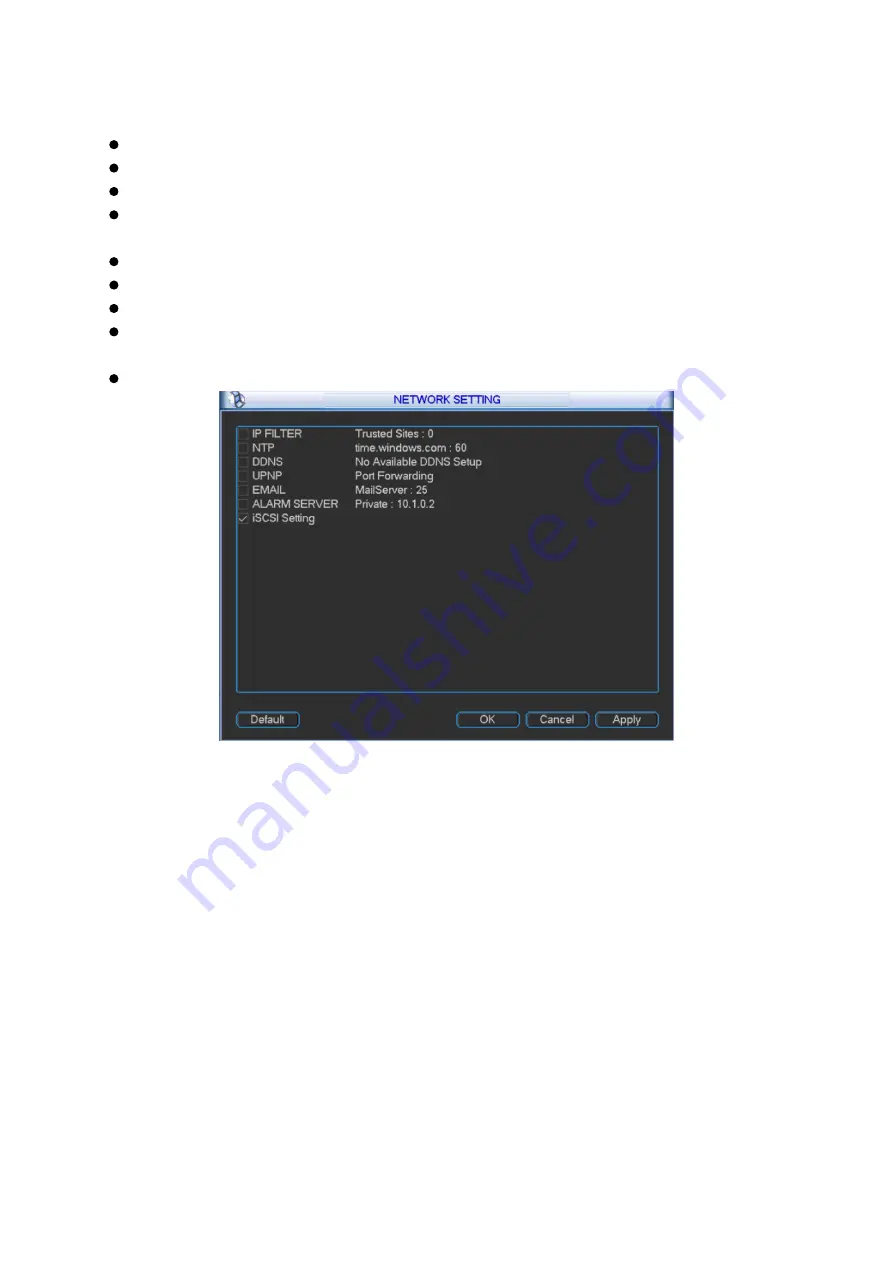
LAN service: Click to enter LAN service setting as shown in Figure 3- 40.
Figure 3- 40
3.2.4.5.1 IP Filter
Only IP listed on trusted sites can connect to this device. Trusted sites supports up to 64 IP
addresses.
If you disable trusted sites, then there will be no limit for IP address to visits this device. Please
see Figure 3- 41.
Summary of Contents for KSC-USB-NET
Page 1: ...i Video Matrix Platform V 2 0 0 ...
Page 4: ...iv 5 DSS OPERATION 169 6 FAQ 170 6 1 FAQ 170 6 2 Maintenance 173 APPENDIX A MOUSE CONTROL 174 ...
Page 34: ...28 Figure 3 9 Switch to input device list Please see Figure 3 9 ...
Page 37: ...31 Figure 3 12 Step 2 Click add You will see Figure 3 13 Figure 3 13 ...
Page 70: ...64 Figure 3 54 Buzzer Buzzer rings when motion detection alarms 3 2 4 6 2 Video Loss ...
Page 74: ...68 Display is shown below as in Figure 3 59 Figure 3 60 and Figure 3 61 Figure 3 59 ...
Page 75: ...69 Figure 3 60 ...
Page 88: ...82 Figure 3 80 Click Add to add new Raid Select corresponding level Figure 3 81 ...
Page 139: ...133 Figure 4 68 Figure 4 69 ...
Page 148: ...142 Figure 4 81 Select slot and channel OSD Custom Step 1 Check Custom OSD see Figure 4 82 ...
Page 173: ...167 ...
Page 174: ...168 ...
Page 182: ......
Page 183: ......
Page 184: ......
Page 185: ......
Page 186: ......
Page 187: ......
Page 188: ......