


63
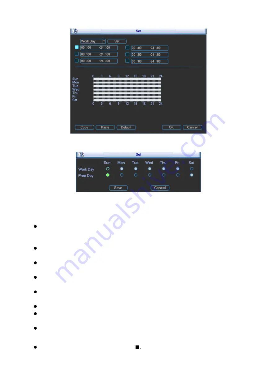
Figure 3- 52
Figure 3- 53
Anti-jitter: Here you can set anti-jitter time. If anti jitter is set to be 10s, then when motion
detect is triggered, this signal will lasts 10s. Currently this function is on motion detect only.
The value ranges from 5 to 600s.
Alarm output: Select alarm output channel (reselectable). When alarm occurs, system will
automatically enable this alarm channel.
Delay: When motion ends, alarm delays for a certain period before it stops. Unit is second
with range between 10 to 300.
Show message: System can pop up a message to alarm you in the local host screen if you
enabled this function.
Alarm upload: System can upload the alarm signal to the network (including alarm centre) if
you enabled this function.
Send email: System can send out email to alert you when alarm occurs.
Record channel: Select designated record channel (same channel can be selected more
than once). When alarm occurs, system will automatically record selected channel.
Delay: When motion detect stops, recording will continue for a set period of time which
ranges from 10s to 300s.
Snapshot: Enable snapshot by checking
Snapshot when motion detection starts. Click
select to set certain channels. See Figure 3- 54.
Summary of Contents for KSC-USB-NET
Page 1: ...i Video Matrix Platform V 2 0 0 ...
Page 4: ...iv 5 DSS OPERATION 169 6 FAQ 170 6 1 FAQ 170 6 2 Maintenance 173 APPENDIX A MOUSE CONTROL 174 ...
Page 34: ...28 Figure 3 9 Switch to input device list Please see Figure 3 9 ...
Page 37: ...31 Figure 3 12 Step 2 Click add You will see Figure 3 13 Figure 3 13 ...
Page 70: ...64 Figure 3 54 Buzzer Buzzer rings when motion detection alarms 3 2 4 6 2 Video Loss ...
Page 74: ...68 Display is shown below as in Figure 3 59 Figure 3 60 and Figure 3 61 Figure 3 59 ...
Page 75: ...69 Figure 3 60 ...
Page 88: ...82 Figure 3 80 Click Add to add new Raid Select corresponding level Figure 3 81 ...
Page 139: ...133 Figure 4 68 Figure 4 69 ...
Page 148: ...142 Figure 4 81 Select slot and channel OSD Custom Step 1 Check Custom OSD see Figure 4 82 ...
Page 173: ...167 ...
Page 174: ...168 ...
Page 182: ......
Page 183: ......
Page 184: ......
Page 185: ......
Page 186: ......
Page 187: ......
Page 188: ......