


5
ON/OFF button.
Device power indicator.
Off: Not operating after plugged in.
Red: Operating.
Device alarm indicator.
Red: Alarm on.
Off: Alarm off.
Device status indicator.
Yellow: Device is properly running.
Air intake of host with dust filter at rear;
Intelligent temperature-controlled fan, total of 2 groups, allow hot swap;
Function Card
Function Card
Control panel s rear slot, marked as C .
Duel-power module, support 220V modules.
1.4.2
Main Control Panel
1.4.2.1
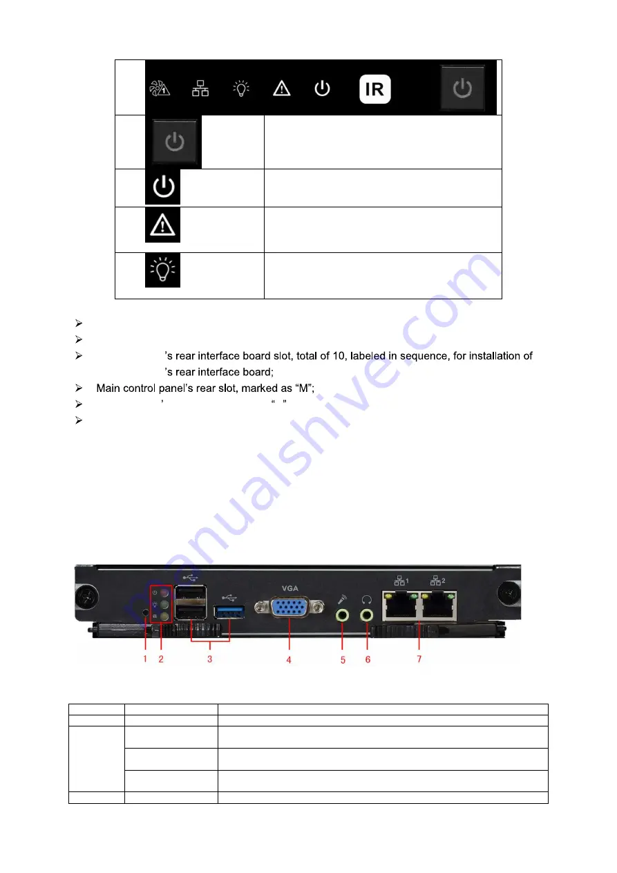
Interface Introduction
Please see Figure 1- 3.
Figure 1- 3
No.
Interface
Function
1
Reset Button
1, support restoring to default settings
2
Mainboard Power
Indicator
1, display mainboard power status
System Status
Indicator
1, display system working status
PCI-E Status
Indicator
1, display PCI-E working status
3
USB Port
3, as 1 USB 3.0 and 2 USB 2.0 for connection to mouse, keyboard, USB
Summary of Contents for KSC-USB-NET
Page 1: ...i Video Matrix Platform V 2 0 0 ...
Page 4: ...iv 5 DSS OPERATION 169 6 FAQ 170 6 1 FAQ 170 6 2 Maintenance 173 APPENDIX A MOUSE CONTROL 174 ...
Page 34: ...28 Figure 3 9 Switch to input device list Please see Figure 3 9 ...
Page 37: ...31 Figure 3 12 Step 2 Click add You will see Figure 3 13 Figure 3 13 ...
Page 70: ...64 Figure 3 54 Buzzer Buzzer rings when motion detection alarms 3 2 4 6 2 Video Loss ...
Page 74: ...68 Display is shown below as in Figure 3 59 Figure 3 60 and Figure 3 61 Figure 3 59 ...
Page 75: ...69 Figure 3 60 ...
Page 88: ...82 Figure 3 80 Click Add to add new Raid Select corresponding level Figure 3 81 ...
Page 139: ...133 Figure 4 68 Figure 4 69 ...
Page 148: ...142 Figure 4 81 Select slot and channel OSD Custom Step 1 Check Custom OSD see Figure 4 82 ...
Page 173: ...167 ...
Page 174: ...168 ...
Page 182: ......
Page 183: ......
Page 184: ......
Page 185: ......
Page 186: ......
Page 187: ......
Page 188: ......