


49
Video/audio: You can enable or disable the video/audio. Main bit stream video by default is
ON. For extra bit stream, you must select video prior to selecting audio.
Audio format: You can select audio format: G711a, G711u and PCM.
Note: In encode setup, you cannot set encode parameter for remote device.
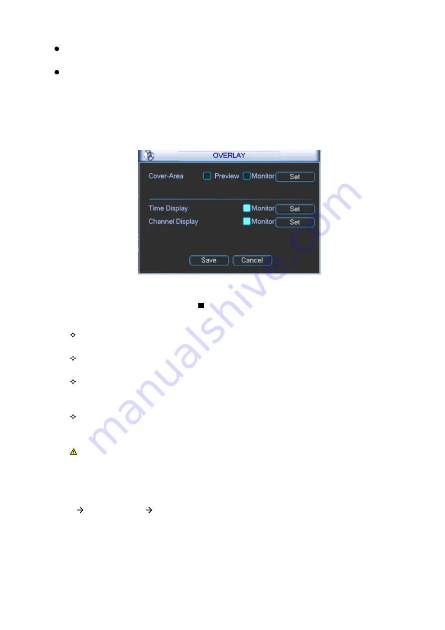
3.2.4.2.1 Overlay
Click overlay button, you can see an interface shown in Figure 3- 35.
Figure 3- 35
Cover area (Privacy mask): Display as . To set cover area. You can drag you mouse to set
proper area size. In one channel video, system max supports 4 zones in one channel.
Preview: Preview means the cover area cannot be viewed by user when system is in
preview status.
Monitor: Monitor means the cover area cannot be view by the user when system is in
monitoring status.
Time display: You can select whether system displays time or not in decoding data for
playback. Please set button and then drag the title to the corresponding position in the
screen.
Channel display: You can select whether system displays channel number or not in
decoding data for playback. Please click set button and then drag the title to the
corresponding position in the screen.
Note: Titles cannot overlay each other.
3.2.4.3
Schedule
After system booted up, it is in default of not recording. You can set record type and time in
menu system settings schedule. Please see Figure 3- 36.
Summary of Contents for KSC-USB-NET
Page 1: ...i Video Matrix Platform V 2 0 0 ...
Page 4: ...iv 5 DSS OPERATION 169 6 FAQ 170 6 1 FAQ 170 6 2 Maintenance 173 APPENDIX A MOUSE CONTROL 174 ...
Page 34: ...28 Figure 3 9 Switch to input device list Please see Figure 3 9 ...
Page 37: ...31 Figure 3 12 Step 2 Click add You will see Figure 3 13 Figure 3 13 ...
Page 70: ...64 Figure 3 54 Buzzer Buzzer rings when motion detection alarms 3 2 4 6 2 Video Loss ...
Page 74: ...68 Display is shown below as in Figure 3 59 Figure 3 60 and Figure 3 61 Figure 3 59 ...
Page 75: ...69 Figure 3 60 ...
Page 88: ...82 Figure 3 80 Click Add to add new Raid Select corresponding level Figure 3 81 ...
Page 139: ...133 Figure 4 68 Figure 4 69 ...
Page 148: ...142 Figure 4 81 Select slot and channel OSD Custom Step 1 Check Custom OSD see Figure 4 82 ...
Page 173: ...167 ...
Page 174: ...168 ...
Page 182: ......
Page 183: ......
Page 184: ......
Page 185: ......
Page 186: ......
Page 187: ......
Page 188: ......