


25
Chart 3- 3
3.1.7
Display Control Area Introduction
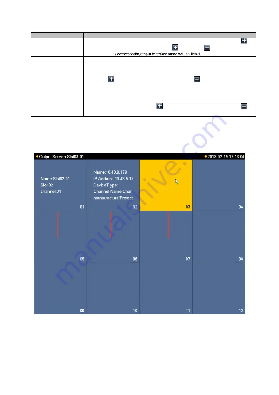
The display control area is shown as follows; please see Figure 3- 6 and Chart 3- 4.
Figure 3- 6
No.
Name
Function Description
1
Decoding Card
List Area
List of Decoding Card inserted in slot, when an Decoding Card is inserted into current slot,
will display. You may click it to extend the list as
will change to
. Meanwhile the current
Decoding Card
2
Input Interface
List Area
Display all input interface names under current Decoding Card. After control area displays, select
channel. By double clicking input interface name, you may switch from local input channel to
currently selected input channel.
3
Remote Input List
Area
Display added remote device list, and devices may be DVR, IPC and otherencoding devices. It
will display
icon, and you may click it to extend the list as
. Meanwhile channels
supported by current remote device will be listed.
4
Remote Input
Channel List Area
Display all input channel names under surrent remote device. After control area displays, select
channel. By double click input interface name, you switch from remote input channel to currently
selected input channel.
5
Input Group
When there is input group, it will display
icon and you may click it to extend the list as
.
Current input group name will be displayed.
1
2
3
Summary of Contents for KSC-USB-NET
Page 1: ...i Video Matrix Platform V 2 0 0 ...
Page 4: ...iv 5 DSS OPERATION 169 6 FAQ 170 6 1 FAQ 170 6 2 Maintenance 173 APPENDIX A MOUSE CONTROL 174 ...
Page 34: ...28 Figure 3 9 Switch to input device list Please see Figure 3 9 ...
Page 37: ...31 Figure 3 12 Step 2 Click add You will see Figure 3 13 Figure 3 13 ...
Page 70: ...64 Figure 3 54 Buzzer Buzzer rings when motion detection alarms 3 2 4 6 2 Video Loss ...
Page 74: ...68 Display is shown below as in Figure 3 59 Figure 3 60 and Figure 3 61 Figure 3 59 ...
Page 75: ...69 Figure 3 60 ...
Page 88: ...82 Figure 3 80 Click Add to add new Raid Select corresponding level Figure 3 81 ...
Page 139: ...133 Figure 4 68 Figure 4 69 ...
Page 148: ...142 Figure 4 81 Select slot and channel OSD Custom Step 1 Check Custom OSD see Figure 4 82 ...
Page 173: ...167 ...
Page 174: ...168 ...
Page 182: ......
Page 183: ......
Page 184: ......
Page 185: ......
Page 186: ......
Page 187: ......
Page 188: ......