User Guide
164
www.bull.com
POST Error Pause Option
For POST error(s) that are listed as Pause, the BIOS enters the error manager and waits
for the user to press an appropriate key before booting the operating system or entering
BIOS Setup.
The user can override this option by setting POST Error Pause to disabled in the BIOS Setup utility Main menu page. If POST Error
Pause is set to disabled, the system will boot the operating system without user-intervention. The default value is set to enabled.
Diagnostic LEDs
During the system boot process, the BIOS executes a number of platform configuration
processes, each of which is assigned a specific hex POST code number. As each
configuration routine is started, the BIOS displays the POST code to the POST Code
Diagnostic LEDs on the back edge of the server board. To assist in troubleshooting a
system hang during the POST process, you can use the Diagnostic LEDs to identify the
last POST process that was executed.
Each POST code is represented by the Eight amber Diagnostic LEDs. The POST codes
are divided into two nibbles, an upper nibble and a lower nibble. The upper nibble bits
are represented by Diagnostic LEDs #4, #5, #6, and #7. The lower nibble bits are
represented by Diagnostics LEDs #0, #1, #2, and #3. Given the bit is set in the upper
and lower nibbles, then corresponding LED is lit. If the bit is clear, corresponding LED
is off.
The Diagnostic LED #7 is labeled as “MSB”, and the Diagnostic LED #0 is labeled
with “LSB”.
Figure 65: Diagnostic LED Placement Diagram
In the following example, the BIOS sends a value of ACh to the diagnostic LED
decoder. The LEDs are decoded as follows.
A. ID LED
F. Diagnostic LED #4
B. Status LED
G. Diagnostic LED #3
C. Diagnostic LED #7 (MSB LED)
H. Diagnostic LED #2
D. Diagnostic LED #6
I. Diagnostic LED #1
E. Diagnostic LED #5
J. Diagnostic LED #0 (LSB LED)
Summary of Contents for NovaScale T840 E2
Page 1: ...NovaScale T840 E2 User s Guide NOVASCALE REFERENCE 86 A1 43FB 01 ...
Page 2: ......
Page 34: ...User Guide 34 www bull com ...
Page 58: ...User Guide 58 www bull com 3 5 HDD cover 3 metric screws M4 Figure 16 Securing the HDD cover ...
Page 112: ...User Guide 112 www bull com Refer to Advanced Menu on page 174 for more information ...
Page 130: ...User Guide 130 www bull com The installation is completed ...
Page 134: ...User Guide 134 www bull com Installing the Operating System without Express Setup ...
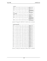
Page 169: ...User Guide 169 www bull com Figure 76 Diagnostic LED POST Code Decoder continued ...
Page 209: ......
Page 210: ...BULL CEDOC 357 AVENUE PATTON B P 20845 49008 ANGERS CEDEX 01 FRANCE REFERENCE 86 A1 43FB 01 ...


