


2007 Buell Ulysses: Electrical
7-61
HOME
Speedometer Needle Sweep Test
NOTE
Speedometer needle sweep test works on the speedometer
only. Use the diagnostics available with DIGITAL TECHNI-
CIAN (Part No. HD-44750) to test a tachometer.
The tester’s sweep function moves the speedometer needle
through the full range of movement. This allows for testing the
smoothness of operation and checking for hesitancy or a
stuck needle.
1.
See
Figure 7-73.
Disconnect vehicle speed sensor con-
nector [65]. Attach speedometer tester connector to vehi-
cle speed sensor connector.
2.
Place speedometer tester power switch in the ON posi-
tion. Place signal switch in the OUT position.
3.
Turn vehicle ignition switch ON.
4.
Begin test by pressing 0 on the tester keypad, then
pressing ENTER. The tester will scan for two seconds,
then the tester will put out a 1 Hz signal.
5.
Select a test range.
a.
Press 2 to select LO range (1-20 Hz).
b.
Press 5 to select CEN range (21-999 Hz).
c.
Press 8 to select HI range (1000-20,000 Hz).
6.
After selecting a range, use the corresponding arrow
keys to accelerate through the range. As you move
through the speed range, check for smooth needle
movement.
a.
If testing LO range, press 1 or 3.
b.
If testing CEN range, press 4 or 6.
c.
If testing HI range, press 7 or 9.
Speedometer Sensor Test
If the speedometer is inoperative, but backlighting and odom-
eter work, the speedometer sensor may not be working.
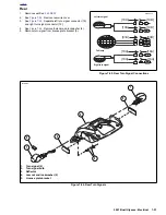
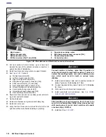
See
Figure 7-74.
Fabricate a test harness using the following
parts. This harness can also be used to test the tachometer.
●
Two Deutsch 3-place socket housings (Part No. 72113-
94BK) and six socket terminals (Part No. 72191-94).
●
Deutsch 3-place pin housing (Part No. 72103-94BK) and
three pin terminals (Part No. 72080-99Y).
●
Six lengths of 18 gauge wire, each 6.0 in. (15 cm) long.
●
Test for voltage to sensor by checking for 4-6 VDC on
red/white wire in connector [65].
●
Then check for continuity to ground on black wire in con-
nector [65].
1.
Install the test harness between the vehicle speed sen-
sor connector halves [65].
2.
Raise rear wheel off floor.
3.
Place speedometer tester power switch in the ON posi-
tion. Place signal switch in the IN position.
4.
Plug the speedometer tester into the test harness. Turn
vehicle ignition switch ON.
5.
Press ENTER on the tester keypad.
6.
Rotate the motorcycle’s rear wheel.
a. If reading on speedometer tester changes as wheel
is rotated, speedometer sensor is OK.
b.
If reading does not change, vehicle speed sensor is
suspect. Install a known, good vehicle speed sensor
and test again.
Figure 7-74. Test Harness
1.
Deutsch socket housing (2)
2.
Deutsch pin housing
1
2
b0779x7x
1
Summary of Contents for 2007 ULYSSES
Page 17: ...A 16 2007 Buell Ulysses Appendix A HOME NOTES ...
Page 51: ...D 2 2007 Buell Ulysses Appendix D HOME Figure D 2 Rear Brake Systems Top View b1115acsxu ...
Page 63: ...D 14 2007 Buell Ulysses Appendix D HOME NOTES ...
Page 73: ......
Page 103: ...1 30 2007 Buell Ulysses Maintenance HOME NOTES ...
Page 129: ......
Page 237: ...2 108 2007 Buell Ulysses Chassis HOME NOTES ...
Page 239: ......
Page 309: ...3 70 2007 Buell Ulysses Engine HOME NOTES ...
Page 347: ...3 108 2007 Buell Ulysses Engine HOME NOTES ...
Page 391: ...4 42 2007 Buell Ulysses Fuel System HOME NOTES ...
Page 481: ......
Page 505: ......
Page 561: ...6 56 2007 Buell Ulysses Drive Transmission HOME NOTES ...
Page 563: ......
Page 587: ...7 24 2007 Buell Ulysses Electrical HOME NOTES ...
Page 645: ...7 82 2007 Buell Ulysses Electrical HOME NOTES ...
Page 647: ......