


5-2
2007 Buell Ulysses: Starter
HOME
ELECTRIC STARTER SYSTEM
5.2
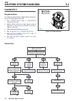
GENERAL
The starter is made up of an armature, field winding assem-
bly, solenoid, drive assembly, idler gear and drive housing.
The starter motor torque is increased through gear reduction.
The gear reduction consists of the drive pinion on the arma-
ture, an idler gear and a clutch gear in the drive housing. The
idler gear is supported by rollers. The clutch gear is part of
the overrunning clutch/drive assembly.
The overrunning clutch is the part which engages and drives
the clutch ring gear. It also prevents the starter from overrun-
ning. The field windings are connected in series with the
armature through brushes and commutator segments.
Wiring Diagrams
For additional information concerning the starting system cir-
cuit, see the wiring diagram at the end of Section 7, ELEC-
TRICAL.
Starter Relay
The starter relay is not repairable. Replace the unit if it fails.
Starter Interlock
See
7.5 STARTER INTERLOCK
for operation and trouble-
shooting information.
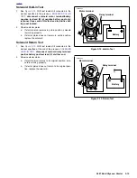
OPERATION
See
Figure 5-1.
When the starter switch is pushed, the starter
relay is activated and battery current flows into the pull-in
winding (10) and the hold-in winding (11), to ground.
The magnetic forces of the pull-in and hold-in windings in the
solenoid push the plunger (7) causing it to shift to the left.
This action engages the pinion gear (1) with the clutch ring
gear (13). At the same time, the main solenoid contacts (8)
are closed, so battery current flows directly through the field
windings (3) to the armature (4) and to ground. Simulta-
neously, the pull-in winding (10) is shorted.
The current continues flowing through the hold-in winding
(11) keeping the main solenoid contacts (8) closed. At this
point, the starter begins to crank the engine.
After the engine has started, the pinion gear (1) turns freely
on the pinion shaft through the action of the overrunning
clutch (12). The overrunning clutch prevents the clutch ring
gear (13) (which is now rotating under power from the engine)
from turning the armature (4) too fast.
When the starter switch is released, the current of the hold-in
winding (11) is fed through the main solenoid contacts (8) and
the direction of the current in the pull-in winding (10) is
reversed. The solenoid plunger (7) is returned to its original
position by the return spring, which causes the pinion gear (1)
to disengage from the clutch ring gear (13).
Summary of Contents for 2007 ULYSSES
Page 17: ...A 16 2007 Buell Ulysses Appendix A HOME NOTES ...
Page 51: ...D 2 2007 Buell Ulysses Appendix D HOME Figure D 2 Rear Brake Systems Top View b1115acsxu ...
Page 63: ...D 14 2007 Buell Ulysses Appendix D HOME NOTES ...
Page 73: ......
Page 103: ...1 30 2007 Buell Ulysses Maintenance HOME NOTES ...
Page 129: ......
Page 237: ...2 108 2007 Buell Ulysses Chassis HOME NOTES ...
Page 239: ......
Page 309: ...3 70 2007 Buell Ulysses Engine HOME NOTES ...
Page 347: ...3 108 2007 Buell Ulysses Engine HOME NOTES ...
Page 391: ...4 42 2007 Buell Ulysses Fuel System HOME NOTES ...
Page 481: ......
Page 505: ......
Page 561: ...6 56 2007 Buell Ulysses Drive Transmission HOME NOTES ...
Page 563: ......
Page 587: ...7 24 2007 Buell Ulysses Electrical HOME NOTES ...
Page 645: ...7 82 2007 Buell Ulysses Electrical HOME NOTES ...
Page 647: ......