


2007 Buell Ulysses: Chassis
2-13
HOME
ASSEMBLY
1.
Install new wheel bearings (2) into hub using suitable
driver. Press on outer race only.
NOTE
●
Press the rotor side bearing in first ensuring it is seated
on the shoulder of the wheel. Followed by pressing the
alternate side until it contacts the spacer.
●
The Wheel Bearing Remover and Installer (B-43993-50)
consists of the Front Wheel Bearing Remover Collet (B-
43993-7), Rear Wheel Bearing Remover Collet (B-
43993-8), Rear Wheel Bearing Installer (B-43993-9),
Front Wheel Bearing Installer (B-43993-10) and Backing
Plates (B-43993-11 front wheel) and (B-43993-12 rear
wheel).
1
1
WARNING
1
WARNING
Be sure that brake fluid or other lubricants do not con-
tact brake pads or discs. Such contact can adversely
affect braking ability, which could cause loss of control,
resulting in death or serious injury. (00290a)
Bearing Installation
NOTES
●
Press the rotor side bearings in first ensuring it is seated
on the shoulder of the wheel. Followed by pressing the
alternate side until it contacts the spacer.
●
Always install the brake side bearing first with the letter-
ing facing out from the hub.
The following procedure describes the bearing installation for
the front wheel; the procedure for the rear wheel is the same.
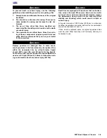
1.
See
Figure 2-12.
Install the Backing Plate (Part No. B-
43993-11) onto the long forcing screw from the Wheel
Bearing Installer/Remover (Part No. HD-44060), with the
smaller diameter toward the wheel hub. Insert the forcing
screw and backing plate into the wheel hub.
2.
See
Figure 2-13.
Sparingly apply EXTREME PRES-
SURE LUBRICANT (Part No. J-23444-A) to the threads
of the long forcing screw (1) to prolong service life and
ensure smooth operation.
3.
Insert a new wheel bearing (2) squarely into the hub,
with the lettered side facing out (away from the wheel).
4.
Slide the FRONT BEARING INSTALLER (Part No. B-
43993-9, from kit Part No. B-43993-50) (3) onto the forc-
ing screw (1), with the smaller diameter toward the bear-
ing bore.
5.
Install a washer (4), Nice bearing (5) and nut (6) onto the
forcing screw (1).
6.
While holding the forcing screw (1), tighten the nut (6)
until the bearing is seated firmly against the shoulder
inside the bearing bore in the wheel hub.
7.
Remove the nut, bearing, washer, FRONT BEARING
INSTALLER (Part No. B-43993-9) and forcing screw.
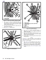
Figure 2-12. Install the Backing Plate (B-43993-12)
and Forcing Screw
i04281
1.
Backing plate
2.
Forcing screw
1
2
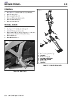
Figure 2-13. Installing Wheel Bearings
i04285
1.
Long forcing screw
2.
Wheel bearing
3.
Front Wheel Bearing Installer (Part No. B-43993-9)
4.
Washer
5.
Nice bearing
6.
Nut
5
1
6
3
4
2
Summary of Contents for 2007 ULYSSES
Page 17: ...A 16 2007 Buell Ulysses Appendix A HOME NOTES ...
Page 51: ...D 2 2007 Buell Ulysses Appendix D HOME Figure D 2 Rear Brake Systems Top View b1115acsxu ...
Page 63: ...D 14 2007 Buell Ulysses Appendix D HOME NOTES ...
Page 73: ......
Page 103: ...1 30 2007 Buell Ulysses Maintenance HOME NOTES ...
Page 129: ......
Page 237: ...2 108 2007 Buell Ulysses Chassis HOME NOTES ...
Page 239: ......
Page 309: ...3 70 2007 Buell Ulysses Engine HOME NOTES ...
Page 347: ...3 108 2007 Buell Ulysses Engine HOME NOTES ...
Page 391: ...4 42 2007 Buell Ulysses Fuel System HOME NOTES ...
Page 481: ......
Page 505: ......
Page 561: ...6 56 2007 Buell Ulysses Drive Transmission HOME NOTES ...
Page 563: ......
Page 587: ...7 24 2007 Buell Ulysses Electrical HOME NOTES ...
Page 645: ...7 82 2007 Buell Ulysses Electrical HOME NOTES ...
Page 647: ......