


3-80
2007 Buell Ulysses: Engine
HOME
CRANKCASE BREATHING SYSTEM
3.13
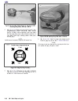
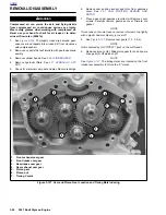
GENERAL
See
Figure 3-114.
Pressure created in the flywheel area on
piston downstroke is released through the
reed valve
into the
gearcase. From there a mixture of crankcase air and oil mist
is vented up the push rod covers to the upper rocker box.
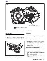
See
Figure 3-115.
Air is allowed to escape the rocker boxes
by exiting the positive crankcase vent (PCV) valves (4)
located on top of the rocker boxes. From the PCV valves the
air enters the crankcase breather hoses (2 & 3). The crank-
case breather hoses route through the air cleaner base plate
(1) to the air box where it is directed inside the air filter ele-
ment and back into the engine.
The oil mist collects and eventually returns to the crankcase
through oil passageways in the cylinder head.
Figure 3-114. Reed Valve Assembly in Gearcase
8661
Figure 3-115. Crankcase Breathing System,
1.
Base plate, air box
2.
Breather hose, rear
3.
Breather hose, front
4.
PCV Valves (2)
5.
Grommet
6.
Rocker cover (2)
3
2
4
5
1
6
b0974b3x
Summary of Contents for 2007 ULYSSES
Page 17: ...A 16 2007 Buell Ulysses Appendix A HOME NOTES ...
Page 51: ...D 2 2007 Buell Ulysses Appendix D HOME Figure D 2 Rear Brake Systems Top View b1115acsxu ...
Page 63: ...D 14 2007 Buell Ulysses Appendix D HOME NOTES ...
Page 73: ......
Page 103: ...1 30 2007 Buell Ulysses Maintenance HOME NOTES ...
Page 129: ......
Page 237: ...2 108 2007 Buell Ulysses Chassis HOME NOTES ...
Page 239: ......
Page 309: ...3 70 2007 Buell Ulysses Engine HOME NOTES ...
Page 347: ...3 108 2007 Buell Ulysses Engine HOME NOTES ...
Page 391: ...4 42 2007 Buell Ulysses Fuel System HOME NOTES ...
Page 481: ......
Page 505: ......
Page 561: ...6 56 2007 Buell Ulysses Drive Transmission HOME NOTES ...
Page 563: ......
Page 587: ...7 24 2007 Buell Ulysses Electrical HOME NOTES ...
Page 645: ...7 82 2007 Buell Ulysses Electrical HOME NOTES ...
Page 647: ......