


3-14
2007 Buell Ulysses: Engine
HOME
ASSEMBLY
NOTES
●
If exhaust header was removed during service it must be
torqued with the engine rotated in the down position. It is
not possible to reach fasteners on the rear exhaust at the
head with engine rotated in the up position.
●
Tighten the front head pipe first. Tighten header nuts
gradually, alternating between studs to insure that
exhaust rings are flush with engine. Tighten fasteners to
72-96 in-lbs (8.1-10.8 Nm).
●
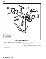
If any oil line fittings are found to be loose, or not oriented
in the proper position, those fittings must be removed
and thoroughly cleaned. After cleaning, apply LOCTITE
565 Sealant to the fitting and re-install to the correct ori-
entation. When tightening oil lines, always support the oil
line fitting with a wrench to maintain proper orientation
and prevent damage to the oil line fitting.
1.
When repairs have been completed, rotate engine back
up into frame.
NOTE
When installing and tightening front isolator bolt it is important
to keep load off of isolator bolt for installation purposes. Alter-
nate between tightening front isolator bolt and raising engine
with scissors jack.
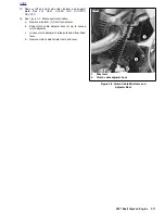
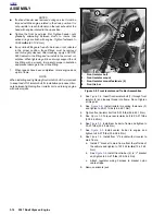
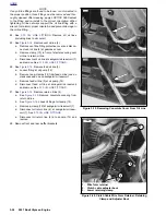
2.
See
Figure 3-8.
Insert front isolator bolt (1) through front
isolator (2) and loosely thread into frame. Do not tighten
at this point.
3.
See
Figure 3-8.
Install isolator mounting fasteners (3)
and tighten to 49-51 ft-lbs (66.4-69.1 Nm).
4.
Tighten front isolator bolt to 49-51 ft-lbs (66.4-69.1 Nm).
5.
See
Figure 3-5.
Torque rear isolator bolt to 25-27 ft-lbs
(33.9-36.6 Nm).
6.
See
Figure 3-5.
Install rear tie bar to frame and tighten to
25-27 ft-lbs (33.9-36.6 Nm).
7.
See
Figure 3-5.
Install center tie bar to engine and
tighten to 25-27 ft-lbs (33.9-36.6 Nm).
8.
See
Figure 3-5.
Install front “V” bracket with oil cooler to
main frame.
a.
Install “V” bracket to main frame from the left side of
the vehicle and tighten to 120-144 in-lbs (13.6-16.3
Nm).
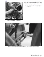
b. See
Figure 3-8.
Install front tie-bar (4) to “V” bracket
and tighten to 25-27 ft-lbs (33.9-36.6 Nm).
c. Attach regulator wiring harness to bracket nylon
cable straps.
9.
Remove scissors jack.
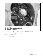
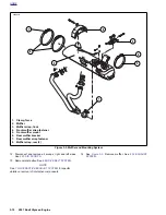
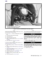
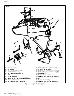
Figure 3-8. Front Isolator and Tie Bar Assemblies
1
2
3
4
1.
Front isolator bolt
2.
Front isolator mount
3.
Front isolator mount fasteners (2)
4.
Front tie bar
10502
Summary of Contents for 2007 ULYSSES
Page 17: ...A 16 2007 Buell Ulysses Appendix A HOME NOTES ...
Page 51: ...D 2 2007 Buell Ulysses Appendix D HOME Figure D 2 Rear Brake Systems Top View b1115acsxu ...
Page 63: ...D 14 2007 Buell Ulysses Appendix D HOME NOTES ...
Page 73: ......
Page 103: ...1 30 2007 Buell Ulysses Maintenance HOME NOTES ...
Page 129: ......
Page 237: ...2 108 2007 Buell Ulysses Chassis HOME NOTES ...
Page 239: ......
Page 309: ...3 70 2007 Buell Ulysses Engine HOME NOTES ...
Page 347: ...3 108 2007 Buell Ulysses Engine HOME NOTES ...
Page 391: ...4 42 2007 Buell Ulysses Fuel System HOME NOTES ...
Page 481: ......
Page 505: ......
Page 561: ...6 56 2007 Buell Ulysses Drive Transmission HOME NOTES ...
Page 563: ......
Page 587: ...7 24 2007 Buell Ulysses Electrical HOME NOTES ...
Page 645: ...7 82 2007 Buell Ulysses Electrical HOME NOTES ...
Page 647: ......