


2007 Buell Ulysses: Drive/Transmission
6-7
HOME
CLUTCH RELEASE MECHANISM
6.3
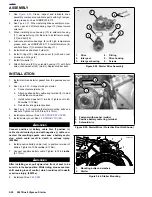
DISASSEMBLY
NOTE
For clutch adjustment procedure, See
1.8 CLUTCH
.
1.
Remove seat. See
2.45 SEAT.
1
1
WARNING
1
WARNING
To prevent accidental vehicle start-up, which could
cause death or serious injury, disconnect negative (-)
battery cable before proceeding. (00048a)
2.
Disconnect negative battery cable.
3.
Slide rubber boot on clutch cable adjuster upward to
expose adjuster mechanism. Loosen jam nut from
adjuster. Turn adjuster to shorten cable housing until
there is a large amount of free play at clutch hand lever.
See
1.8 CLUTCH
.
4.
See
Figure 6-9.
Remove three TORX screws with wash-
ers and clutch inspection cover.
5.
Slide spring (4) with attached screw lockplate (5) from
flats of adjusting screw.
6.
Turn adjusting screw clockwise to release ramp and cou-
pling mechanism (7). As the adjusting screw is turned,
ramp assembly moves forward. Unscrew nut (6) from
end of adjusting screw.
7.
Remove hook of ramp from cable end coupling (10).
Remove cable end from slot in coupling.
8.
Remove and discard retaining ring from ramp assembly
to separate inner and outer halves. Remove three balls
from ramp sockets.
CLEANING AND INSPECTION
1.
Thoroughly clean all parts in cleaning solvent.
2.
See
Figure 6-9.
Inspect three balls of release mecha-
nism and ball socket surfaces of inner and outer ramps
for wear, pitting, surface breakdown and other damage.
Replace parts as necessary.
3.
Check hub fit of inner and outer ramps. Replace ramps if
excessively worn.
4.
Check clutch cable for frayed or worn ends. Replace
cable if damaged or worn.
5.
Change or add transmission fluid if necessary. See
1.8
CLUTCH
.
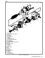
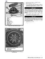
Figure 6-9. Clutch Release Mechanism
b1057b6x
1
2
3
4
7
11
8
5
6
10
1.
TORX screw with washers (3)
2.
Clutch inspection cover
3.
Clutch cover gasket
4.
Spring
5.
Lockplate
6.
Nut
7.
Ramp assembly
8.
Adjusting screw assembly
9.
Primary cover
10. Coupling
11. Drain plug and o-ring
9
Summary of Contents for 2007 ULYSSES
Page 17: ...A 16 2007 Buell Ulysses Appendix A HOME NOTES ...
Page 51: ...D 2 2007 Buell Ulysses Appendix D HOME Figure D 2 Rear Brake Systems Top View b1115acsxu ...
Page 63: ...D 14 2007 Buell Ulysses Appendix D HOME NOTES ...
Page 73: ......
Page 103: ...1 30 2007 Buell Ulysses Maintenance HOME NOTES ...
Page 129: ......
Page 237: ...2 108 2007 Buell Ulysses Chassis HOME NOTES ...
Page 239: ......
Page 309: ...3 70 2007 Buell Ulysses Engine HOME NOTES ...
Page 347: ...3 108 2007 Buell Ulysses Engine HOME NOTES ...
Page 391: ...4 42 2007 Buell Ulysses Fuel System HOME NOTES ...
Page 481: ......
Page 505: ......
Page 561: ...6 56 2007 Buell Ulysses Drive Transmission HOME NOTES ...
Page 563: ......
Page 587: ...7 24 2007 Buell Ulysses Electrical HOME NOTES ...
Page 645: ...7 82 2007 Buell Ulysses Electrical HOME NOTES ...
Page 647: ......