12
BONMET motion GmbH/www.bonmet.com/www.bonmet.de
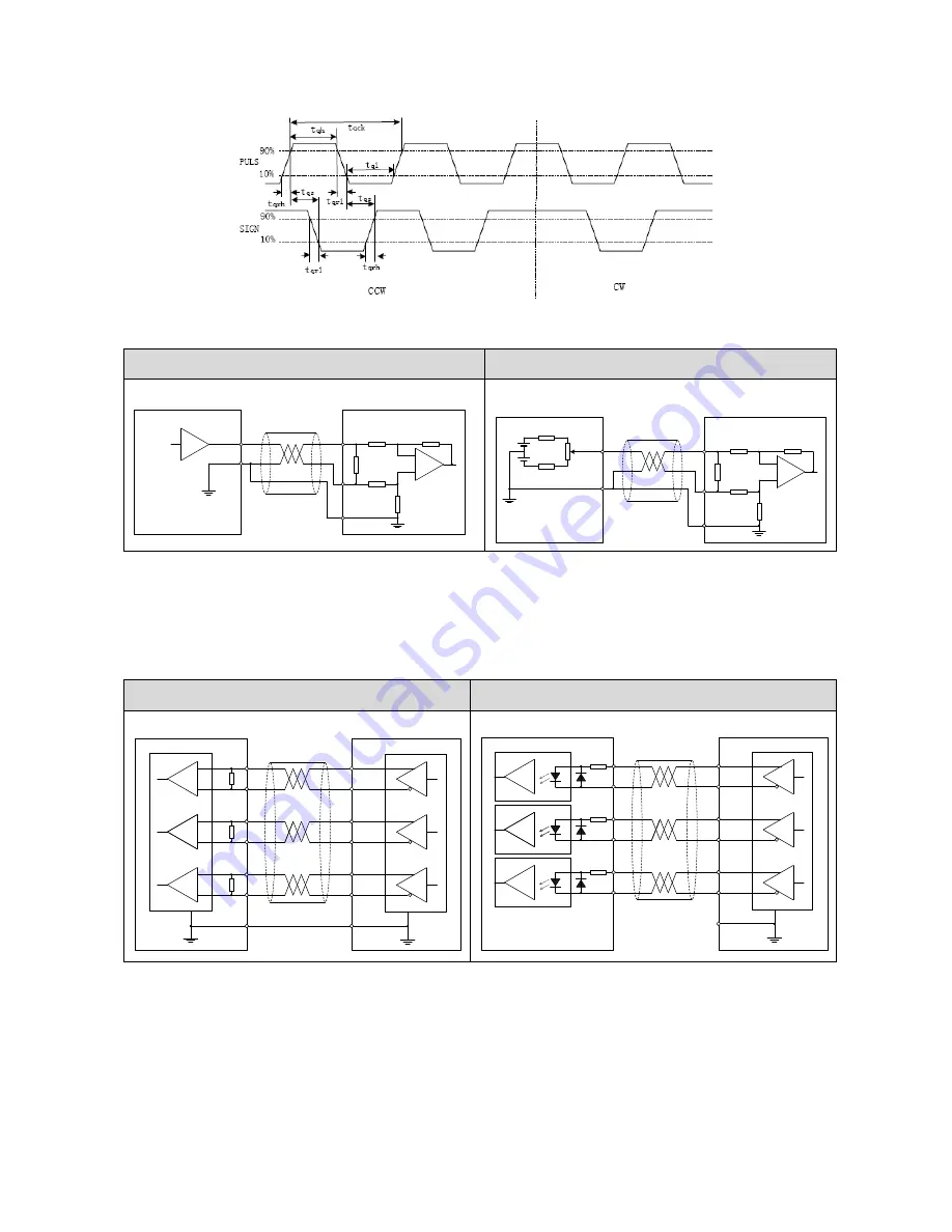
Sequence chart for A/B phase pulse
3.6.4
Wiring of Analog Input
Analog voltage input
Potentiometer input
Note
:
"AO" means analog command.
(1)
AGND must be connected to the ground (0V) of analog command;
(2)
Max. permissible input voltage to each input is ±10V;
(3)
It is suggested that using Shielded twisted pair as the analog input cable;
(4)
Analog input drift is normal, you can use analog input drift compensation function to deal with it..
3.6.5
Wiring of Encoder Differential Output
Wiring of line receiver
Wiring of optocoupler
(1)
Feeds out the divided encoder outputs (A, B and Z-phase) in differential through each line driver.
(2)
Customer can use a line receiver (like AM26LV32). Install a terminal resistor (approx. 330Ω) between line
receiver inputs without fail. And connect ―EGND‖ to the ground (0V) of the receiver.
(3)
Customer can use a optocoupler to receive the signals.
(4)
These outputs are not insulated.
3.4
Servo drive
AO
+
AO
-
Host controler
+
-
+
-
AGND
10KΩ
AO
+
AO
-
Adjust voltage
by potentiometer
+
-
AGND
10KΩ
2KΩ(1/2W)
200Ω(1/2W)
200Ω(1/2W)
10V
10V
Servo drive
Servo drive
PhaseA
+
PhaseA
-
PhaseB
+
PhaseB
-
Host controler
PhaseZ
+
PhaseZ
-
Pin_1
Pin_2
Pin_3
Pin_4
Pin_5
Pin_6
R
EGND
Pin_9
AM26LS31
AM26LV32 or other line receiver
R
R
Servo drive
PhaseA
+
PhaseA
-
PhaseB
+
PhaseB
-
Host controler
PhaseZ
+
PhaseZ
-
Pin_1
Pin_2
Pin_3
Pin_4
Pin_5
Pin_6
220Ω(1/2W)
220Ω(1/2W)
220Ω(1/2W)
EGND
Pin_9
AM26LS31
Optocoupler


