background image

26

BINKS EMS  |  OPERATION MANUAL

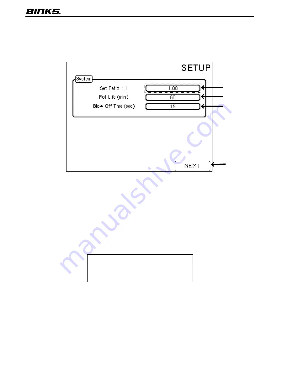
8.11  System Screen

The system screen is used for setting the ratio in a single color system, changing Pot Life time, and adjusting the Blow Off Time.

1.  Set Ratio : 1

  Putting a new value in the box will 

override the programmed value and will hold 
until the system is flushed or another color is 
loaded. Only available on 1 color systems.

2.  Pot Life (min)

  Adjust this number to correspond 

with the amount of time it takes mixed material 
to remain sprayable, represented in minutes. The 
end of the pot life will result in a pot life alarm . 
After resetting the alarm the user will be allowed 
to spray out the material in the line or flush. 

3.  Blow Off Time (sec)

  The allotted time for 

atomizing air to be triggered without spraying 
material. After the time has expired, an alarm 
will sound stating No Resin Flow. Useful for 
blowing contaminants off parts immediately 
prior to spraying.

4.   NEXT

  By pressing F4 (NEXT), it will advance to 

the next screen. 

NOTE

To adjust values, press the down arrow until the variable 
in question is highlighted. Use the number pad on the 
pendant to enter the desired value. After the value is 
displayed press the enter key to accept the value.  

Summary of Contents for E20-1108

Page 1: ...Replaces Part Sheet 77 0000 Part Sheet 77 2980 ELECTRONIC MIX SOLUTIONS Plural Component Mixing System Operation Manual ...

Page 2: ... Usage Screen 8 4 Prime Screen 8 5 Alarm Screen 8 6 Alarm History 8 7 Alarm Help Screen 8 8 PENDANT GUIDE continued Power ON 8 9 Password Prompt 8 10 System Screen 8 11 Set Ratio Screen 8 12 Load Sequence 8 13 Calibration Resin Hardener 8 14 Calibration Resin Only 8 15 Alarm Enables 8 16 Advanced Settings 8 17 Dispense Pump Pressure 8 18 Dispense Pump Calibration 8 19 Passwords 8 20 Gun Flush Box ...

Page 3: ...ON TO THE OPERATOR OF THE EQUIPMENT PROP 65 WARNING WARNING This product contains chemicals known to the State of California to cause cancer and birth defects or other reproductive harm CA PROP 65 HIGH PRESSURE CONSIDERATION High pressure can cause serious injury Relieve all pressure before servicing Spray from the spray gun hose leaks or ruptured components can inject fluid into your body and cau...

Page 4: ...mber of Guns 1 One Gun 2 Two Guns 3 One Gun with Gun Flush Box 4 Two Guns with Gun Flush Boxes Note Does not include 5 32 tubing for flush box pneumatic connections Must designate gun when ordering flush box es If the example number shown above E20 161302 was ordered the customer would receive the following E20 system with 200cc Dispense Pump 6 colors with a Dispense Pump flow sensor one gun with ...

Page 5: ...ements 95 132 VAC 50 60Hz 8 Amp 14 AWG power supply wire gauge Environmental Indoor use pollution degree 2 THE BINKS EMS HAS UNIQUE FEATURES THAT YIELD SUPERIOR MIXING PERFORMANCE Continuous Flow The mix manifold is designed to optimize mix quality and minimize internal volume by receiving Resin Component A and Hardener Component B continuously not in alternating doses Accurate Dispensing Control ...

Page 6: ...ts n Ensure wall is able to support weight of complete system including air and fluid hoses and other connected devices Minimum 200 lbs 91 kg n Ensure clearance for electrical and fluid connections to unit and door swing radius n Bolt frame sections to wall or panel using minimum 4 each of 3 8 lag screws or cap screws with flat washers ...

Page 7: ...6 0 12 TYPICAL 66 0 24 20 RADIUS 3 2 Overall Dimensions shown with optional floor stand Floor stand requirements n Bolting stand to floor or platform is highly recommended Use minimum 4 each of 3 8 lag screws or anchors with flat washers ...

Page 8: ... work must be completed by a qualified electrician and comply with all local and national codes and regulations Fused power disconnect switch is not included with system but is required for installation Control enclosure cannot be placed in a hazardous location Power requirements for the Binks EMS are 95 132 VAC 50 60Hz 15 Amp 8 14 AWG The installation is required to meet the standards of the Nati...

Page 9: ... cord connect power as follows 1 Use existing 7 8 diameter hole on top right of control enclosure as the power port 2 Use a compatible cord grip strain relief 3 Connect power cord to the appropriate terminals as shown at left 4 For the complete electrical schematic please see the electrical diagram section in the Binks EMS Maintenance and Repair Manual 77 2981 Top right corner view of control encl...

Page 10: ...low through these switches will tell the controller to look for resin flow If used with flush boxes the switches will connect to an upstream valve to shut off atomizing air for flushing ITEM DESCRIPTION 5 Mix Manifold Three versions available n Mix Manifold for Multicolor used with multi color valve stack shown n Programmable Flush for single color systems n Manual flush for single color systems 6...

Page 11: ... mode until the Alarms have been reset The mute button on the pendant will disable the audible visual signal however the system will remain in alarm status until reset 4 Enclosure Latch Open or close the cabinet with a screwdriver or coin 5 Power Cord 25 foot power cord with 3 prong plug for connection to 120VAC May be removed for hard wire connection 6 Pendant 3 8 monochrome display with 24 key m...

Page 12: ...ectric signals for use by the PLC board Used with Gun Flush Boxes 6 Stepper Motor drives the Dispense Pump The motion of the pump is controlled by the PLC Board and the Stepper Motor Drive Control ITEM DESCRIPTION 7 Dispense Pump Driven by the motor in the control enclosure the Dispense Pump flows the correct volume of hardener to the mix manifold to provide the correct ratio 8 Dispense Pump Flow ...

Page 13: ...movement of the Dispense Pump 4 Fluid Back Panel The mounting plate used to secure the components to the wall or stand mount ITEM DESCRIPTION 5 Air Flow Switches Senses the atomizing air when the spray gun is triggered One Air Flow Switch is used for each spray gun 6 Mix Manifold The location of Resin and Hardener mixing Combines the two materials and sends the resulting mixture out to the spray g...

Page 14: ... pressure for the control enclosure should range from 75 100 psi 5 to 7 bar for proper actuation of the system poppet valves Air pressure for spray gun atomizing air should be greater than 20 psi 1 5 bar for proper function of the air flow switches Multicolor System Single Color Fluid Panel NOTE Single Color Manual Flush systems will not use A11 or A12 air connections Poppet valves are replaced by...

Page 15: ...y Dispense pump top outlet trigger 5 32 A9 Poly Dispense pump bottom outlet trigger 5 32 A10 Poly Resin Enable trigger 5 32 A11 Poly Flush air trigger 5 32 A12 Poly Flush solvent trigger 5 32 A13 Poly Color 1 trigger 5 32 A14 Poly Color 2 trigger 5 32 A15 Poly Color 3 trigger 5 32 A16 Poly Color 4 trigger 5 32 A17 Poly Color 5 trigger 5 32 A18 Poly Color 6 trigger connection or Gun Flush Box trigg...

Page 16: ... A10 Resin Enable poppet valve and solenoid connection A11 Air enable poppet valve and solenoid connection This connection is made on the color stack when multiple colors are ordered or on the mix manifold when auto flush is ordered with one color A12 Solvent enable poppet valve and solenoid connection This connection is made on the color stack when multiple colors are ordered or on the mix manifo...

Page 17: ...ut 1 to 1 5 turns past finger tight Do not over tighten as exceeding 1 5 turns will likely cause the ferrules to cut through the tubing For pipe threads NPT use PTFE tape or other pipe thread sealant for stainless steel connections If using tape wrap clockwise two to three times around the threads Ensure tape does not protrude beyond threads If using liquid sealant apply sealant bead completely ar...

Page 18: ...et from Dispense Pump 1 4 Compression 1 4 F4 Solvent Inlet Mix Manifold 3 8 NPS male F14 Resin inlet for mix manifold 3 8 Comp 3 8 F15 Mix manifold outlet to static mixer 3 8 Compression F16 Flow meter inlet 1 color 3 8 NPS male F17 Flow meter outlet 1 color 3 8 Compression Single Color Fluid Panel F17 F16 F14 F4 F3 F15 ...

Page 19: ...y F5 Solvent inlet color stack When multiple colors are used the flush solvent inlet is located at the top right side of the color stack A 1 4 NPT male threaded check valve is supplied in the inlet of the color stack Attach solvent supply line to the 3 8 NPS male adapter F6 F11 represent the optional number of colors 1 6 1 5 if two gun flush boxes are used Port threads are 3 8 NPT female Plugs wil...

Page 20: ... and navigate screens Below is a description of the function of each button on the keypad 1 Home This button can be pushed at any time to return the display back to the Home Screen 2 Mute Silence a sounding alarm This button will NOT reset the alarm it will only silence the buzzer until the alarm has been reset 3 Color Used to perform color changes and programmed flush sequences 4 ESC This is used...

Page 21: ... Mode Displays whether the system is in mix standby flush or alarm state 7 Current Color This is the color that is currently loaded Zero will be displayed if solvent is loaded or if a failed color changed occurred 8 Set Ratio This is the pre set ratio defined in the SETUP screen for the current color 9 Current Ratio This is the current real time calculated ratio for the color currently in use 10 P...

Page 22: ...e visible at the bottom of this list In order for the usage totals to be saved before the system is powered down this screen must be accessed Once it is accessed the values will automatically be saved and the Binks EMS can be powered down 1 Current Color This is the current color loaded in the system 2 New Color This is the field where the next color number to load is entered 3 GO The button used ...

Page 23: ... off for successful loading Press F3 again to stop 2 HARDENER By pressing F2 HARDENER once the Dispense Pump valves will open and the Dispense Pump will cycle The gun must be triggered with atomizing air off for successful loading Press F2 again to stop 3 Checkboxes The indicating icon that shows when either the hardener or resin is active 4 Color Valve The icon displaying which Resin valve is bei...

Page 24: ...of the system such as what alarms occurred in a given shift Press F1 HISTORY to access a timeline of alarms and events The last 40 events will be recorded 2 RESET This button will reset all active alarms except for the current pot life Must be pushed if an Alarm has sounded 2 1 The previous event history of the unit is shown on the Alarm History page The previous 40 events are recorded 1 BACK Pres...

Page 25: ...en This screen indicates the current software revision numbers 1 Details A description indicating the unit has been powered on 2 Revision Numbers The current software revision numbers are displayed here 3 BACK To return to the previous page press F4 BACK 1 3 2 8 10 Password Prompt By pressing F4 SETUP on the home screen the prompting page will be displayed asking for a password Enter a password us...

Page 26: ...n minutes The end of the pot life will result in a pot life alarm After resetting the alarm the user will be allowed to spray out the material in the line or flush 3 Blow Off Time sec The allotted time for atomizing air to be triggered without spraying material After the time has expired an alarm will sound stating No Resin Flow Useful for blowing contaminants off parts immediately prior to sprayi...

Page 27: ... or catalyst 2 NEXT Pressing F4 NEXT will advance to the next screen 2 1 NOTE Colors will only be accessible if the system is configured for multicolor To adjust values press the up down arrow until the desired field is highlighted Use the number pad on the pendant to enter the desired value After the value is displayed press the enter key to accept the new value When changing paint resins and or ...

Page 28: ...the duration of the air valve open time until the solvent valve is opened 4 Solvent Chop Time sec This value determines the solvent valve open time until the next air chop 5 Chop Duration sec The total duration of the solvent and air chop 6 Last Flush Press F2 TOGGLE to switch the Last Flush between solvent and air 7 Last Flush Time sec The total duration of the Last Flush 8 Load Volume cc At this...

Page 29: ...olume cc This is a user input Enter the measured volume after triggering the gun for a specified time Press F3 Save after entering the Measured Volume 5 Calculated cc pulse After a new measured volume is inputted the new cc pulse will be displayed in this box This is a preview of the new cc pulse The Save button F3 must be pressed to accept the new value 6 START This button F2 will reset the expec...

Page 30: ...d volume after triggering the gun for a specified time Press F3 Save after entering the Measured Volume 5 Calculated cc pulse After a new measured volume is entered the new cc pulse will be displayed in this box This is a preview of the new cc pulse The Save button F3 must be pressed to accept the new value 6 START This button F2 will reset the expected volume and pulse count to zero Press this be...

Page 31: ...replacement arrives 1 Highlighted Alarm Represents the current alarm in question By pressing the arrows on the pendant other alarms can be highlighted and then activated or deactivated by pressing F2 ON OFF 2 ON OFF Button When the alarm is highlighted pushing F2 ON OFF will turn on or off the given alarm If the alarm has a check in the box it is currently active 3 NEXT Pressing F4 NEXT will advan...

Page 32: ...olor unit 5 seconds is recommended 4 Flow Sensor Delay Time sec Represents the ramp up time for the Dispense Pump Flow Sensor During this period of time the unit will monitor the flow of hardener For high ratios where flow is very low a longer time such as 5 10 seconds is recommended 5 Max Resin Flow Rate cc min The limit of resin flow through the flow meter Default is 2000 cc min This limit can v...

Page 33: ...ng these limits closer to the high and low nominal operating pressures will reduce the probability of a balance fault due to improper pressure settings upstream 1 2 3 NOTE This screen is only accessible with the Advanced password 1 Minimum Inlet Pressure psi This sets the low limit in psi that will trigger a Low Inlet Pressure alarm Default is 10 psi 2 Maximum Outlet Pressure psi This sets the hig...

Page 34: ...ment 3 UP limit This number is the upper limit The default value is set between 0 40 and 0 60 4 Current measurement This number displays the current position of the piston This number ranges between 0 and 5 5 DOWN limit This number is the lower limit The default value is set between 4 40 and 4 60 6 SET LIMIT Pushing F3 SET LIMIT will record the position of the piston Push when the indicating flag ...

Page 35: ...l allow access to all options in the set up menus Acceptable password ranges are numbers from 0 to 99999 3 Year Enter the current year 4 Month Enter the current month 5 Date Enter the current date 6 Hour Enter the current hour 7 Minute Enter the current minute 8 Second Enter the current seconds 9 NEXT By pressing F4 NEXT it will advance to the next screen 1 2 3 4 5 6 7 8 9 NOTE This screen is only...

Page 36: ... is enabled for the flush box system A checkmark will appear when the second gun is enabled 3 ON OFF Pressing F2 ON OFF will enable or disable the highlighted gun flush box 4 NEXT Pressing F4 NEXT will advance to the next screen 1 2 3 4 NOTE This screen is only accessible with the advanced password and if the system has been configured with gun flush boxes If the system was not configured with flu...

Page 37: ...on top of the air flow switches A2 For gun atomizing typically 20 75 psi 3 Air flow switch output A3 directly to the spray gun s 4 Air flow switch signal from the individual air switch to pressure switch A21 A22 5 Regulated air supply to mix manifold flushing air A4 or for a multicolor system the color stack flushing air A5 6 If the system is equipped with gun flush boxes a Regulated air supply to...

Page 38: ...s have been adjusted as needed turn the Utility Switch to MIX mode 13 Press the Color button and load the desired color 14 After the completion of the color load energize atomizing air and spray 15 When spraying is complete shut off atomizing air and perform a color change or flush as required Startup for systems with gun flush boxes 1 Turn the utility switch to Standby mode Ensure all compressed ...

Page 39: ...e measured volume into the Measured Volume field and press Enter The program will then display the calculated cc pulse 9 Input the number shown in the calculated cc pulse box into the Flow Meter cc pulse field at the top of the screen 10 Repeat steps 1 9 to verify the new cc pulse value The new Measured Volume should match the Expected Volume If these values match the Flow Meter Calibration has be...

Page 40: ...ir Look for overflowing or hints of hardener catalyst material in the reservoir ________ Check that the system is not in an Alarm state It is possible an Alarm is not allowing the pump to run ________ Visually inspect the ACME threaded rod Look for damage and engagement with the potentiometer gear ________ Verify the flag indicator is tightly securing the ACME rod to the pump rod Inspect the Pump ...

Page 41: ...y If an alarm has occurred verify that the problem has been resolved For Example if the High Output Pressure alarm shows in the list verify there are no pinched hoses or clogged static mixers CAUTION If using a GUN BOX ensure gun is in box with the lid closed If loading a color or flushing without a gun box ensure atomizing air is turned off and trigger material into a grounded metal waste contain...

Page 42: ...sired and press Go to load the color When loading a color if the current color is 0 the fluid lines will not be flushed since it is assumed there is no material in the lines following the 10 5 End of Day Flushing Procedure NOTE For a color change the Go button will not display if The spray gun s are not in the Gun Box es The Gun Box lids are not closed The system is in Standby mode 5 The color sho...

Page 43: ...ration of last flush should be timed to minimize solvent waste but still completely load the fluid lines with solvent Load Volume 300cc Use the chart from 9 2 Power Up Procedure Volume needed to load mixed material into the fluid lines The following factors will influence the choices listed above Worst case flushing Always set up the flush parameters using the most viscous worst case resin materia...

Page 44: ...ot hose B Flush Mode i Turn the Utility Switch to Flush mode until the fluid lines have been cleared of mixed material Perform a color 0 load to fill the fluid lines with solvent Be sure to trigger the gun C Manual Flush Operate air and solvent ball valves until fluid lines are flushed Be sure to trigger the gun i Open Air Flush Valve for 5 seconds while triggering the gun Close Air Flush Valve ii...

Page 45: ...ed to fluid pressure 5 The working fluid in both the Color Stack if equipped and Dispense Pump are under pressure To release this pressure go to the Home Screen and then the Prime screen on the Pendant 6 If not using GFB trigger the gun into a grounded metal waste container Press F2 to engage the Dispense Pump and cycle it to release any built up pressure Allow it to run for 5 seconds and then pre...

Page 46: ...Binks EMS components that requires calibration See 9 3 Flow Meter Calibration Procedure to verify the proper performance of the flow meter Catalyst A coating component that initiates a chemical reaction in the coating to accelerate the hardening process Catalysts are typically identified by high mix ratios such as 10 1 or 50 1 Sometimes the catalyst to resin ratio is expressed as a percentage such...

Page 47: ...mand used to push the piston of the dispense pump downwards and set the limits of operation in the Manufacturing Setup page of the Pendant Setup Jog Up The command used to pull the piston of the dispenser pump upwards and set the limits of operation in the Manufacturing Setup page of the Pendant Setup Load Volume After completing a flushing procedure of the spray guns the load volume is the volume...

Page 48: ...tains a corresponding manifold outlet Seal Assembly The set of plastic packings and adapters that seal the dispenser pump rod to avoid leakage Solenoid The device used to convert electrical signals to pneumatic trigger signals for poppet valves Packaged in solenoid stacks for compact location of trigger control Can be manually triggered if needed Solvent The material used to clean mixed material f...

Reviews: