19
126305 Rev B 05/22/15
Once in Manager’s Mode press the numeric [2] key and
press the function [Enter] key.
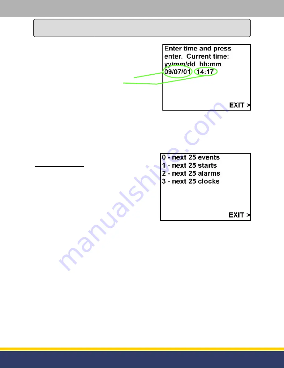
Once the function [Enter] key is pressed the display will show
what the current date and time is set for (see figure 4.3).
The date in figure 4.3 is showing July 1st, 2009.
The time in figure 4.3 is showing 2:17 P.M.
To change the date and time start with entering the last two
digits of the year, the two digits for the month, the two digits
for the day, next enter the two digits for the hour (military
time) and the two digits for the minutes. When this is
complete press the function [Enter] key to save the new
setting.
After this is complete press the right Soft Key where “EXIT” is present on the display to exit Manager’s
Mode 02.
If programming is complete press the right Soft Key next to “EXIT” on the display again and the module
will return to normal operation.
Manager’s Mode 03:
After the RTC has been set the Audit Trail Report will print
the date and time that each event happens. These reports
will tell when each of the Audit Events have taken place.
Once the module is in Manager’s Mode press the numeric
[3] key and press the function [Enter] key.
The display will show four different reports that can be
printed out (see figure 4.4).
1.
The last 25 times any of the Audit Events have occurred.
2.
The last 25 times that the Software has Restarted.
3.
The last 25 times that the Door has been Opened.
4.
The last 25 times that the RTC (Real Time Clock) has been reset.
Press the numeric key that correlates with the desired report and the printer will print out the report.
The unit will store a maximum of 4,032 Audit Events. If more than the last 25 events is desired continue
to press the same numeric key until it prints that event. The report will print the newest events first.
After this is complete press the right Soft Key where “EXIT” is present on the display to exit Manager’s
Mode 03.
If programming is complete press the right Soft Key next to “EXIT” on the display again and the module
will return to normal operation.
Service
(continued...)
Figure 4.3
-
Mode 02
Figure 4.4
-
Mode 03


