


Mounting and wiring
EL70x1
38
Version: 4.4
4
Mounting and wiring
4.1
Installation on mounting rails
WARNING
Risk of electric shock and damage of device!
Bring the bus terminal system into a safe, powered down state before starting installation,
disassembly or wiring of the Bus Terminals!
Assembly
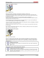
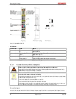
Fig. 20: Attaching on mounting rail
The Bus Coupler and Bus Terminals are attached to commercially available 35 mm mounting rails (DIN rails
according to EN 60715) by applying slight pressure:
1. First attach the Fieldbus Coupler to the mounting rail.
2. The Bus Terminals are now attached on the right-hand side of the Fieldbus Coupler. Join the compo-
nents with tongue and groove and push the terminals against the mounting rail, until the lock clicks
onto the mounting rail.
If the Terminals are clipped onto the mounting rail first and then pushed together without tongue and
groove, the connection will not be operational! When correctly assembled, no significant gap should
be visible between the housings.
Note
Fixing of mounting rails
The locking mechanism of the terminals and couplers extends to the profile of the mounting
rail. At the installation, the locking mechanism of the components must not come into con-
flict with the fixing bolts of the mounting rail. To mount the mounting rails with a height of
7.5 mm under the terminals and couplers, you should use flat mounting connections (e.g.
countersunk screws or blind rivets).
Summary of Contents for EL7031
Page 1: ...Documentation EL70x1 Stepper Motor Terminals 4 4 2017 08 18 Version Date...
Page 2: ......
Page 6: ...Table of contents EL70x1 6 Version 4 4...
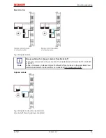
Page 48: ...Mounting and wiring EL70x1 48 Version 4 4 Fig 32 Other installation positions example 2...
Page 96: ...Commissioning EL70x1 96 Version 4 4 Fig 90 Incorrect driver settings for the Ethernet port...
Page 179: ...Commissioning EL70x1 179 Version 4 4 Index 7020 POS Outputs Ch 1...
Page 203: ...Commissioning EL70x1 203 Version 4 4 Index 7020 POS Outputs Ch 1...