


OPERATING PROCEDURES
VIEW CONFIGURATION
WBPEEEUI110501A0
4 - 7
VIEW CONFIGURATION
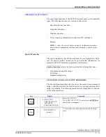
This function key allows the user to view the parameters of the working con-
figuration. Modifications cannot be made to the configuration.
NOTE:
This procedure is similar for all device types. This procedure is
intended as a general guide for this function. Variances occur based on
device type.
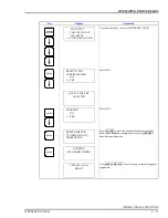
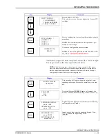
Lower and upper range values are displayed.
Indicator points to the configured initialization mode.
Indicator points to the configured fail mode.
Secondary upper and lower range values are displayed to
the nearest hundredth.
Only applies if interfacing a Type PTS transmitter. The
upper and lower range temperature alarm values are
shown as configured.
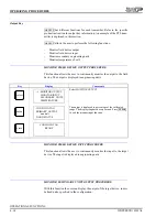
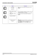
Configuration ID tag name just configured will be in the
upper left corner if the configuration was saved. This
becomes the working configuration.
Key
Display
Comments
ENTER
LOWER RANGE VAL.
nn.nn UNITS
UPPER RANGE VAL.
nn.nn UNITS
ENTER
INITIALIZE MODE:
→
LOW
HIGH
ENTER
FAIL MODE:
→
LOW
HIGH
LAST
ENTER
SECONDARY L. R.
nn.nn UNITS
SECONDARY U. R.
nn.nn UNITS
ENTER
LOWER TEMP ALARM
-50.00°C
UPPER TEMP ALARM
120.00°C
ENTER
CONFIG. ID TAG
READY
Key
Display
Comments
Displays the 14 character ID tag of the connected device.
If using the
ANALOG
mode, the
CHANNEL
field will not
display.
Indicator points to the configured output type.
VIEW
CONFIG. ID TAG
TYPE: PTS
MODE: DIGITAL
CHANNEL: 1
ENTER
OUTPUT TYPE:
LINEAR
→
SQUARE ROOT
3/2 FLOW MODE