background image

0019-9376 

Revision 0

4

Monoxor

®

 XR User Manual

4.5  Ending a Test .................................................................................................................. 42

4.6  Differential Temperature Measurement

 .................................................................... 42

4.7  Timed Ambient CO Testing ........................................................................................... 43
4.8  Printing Using the Optional IrDA Printer .................................................................... 44

4.9  Turning Off the Analyzer

 ............................................................................................... 46

4.10  PC Interface and Fyrite

®

 User Software ...................................................................... 47

Care & Maintenance ...................................... 48

5.1 Serviceability .................................................................................................................. 48
5.2  Cleaning the Probe ........................................................................................................ 49

5.2.1 

Equipment Required ..................................................................................................................................49

5.2.2 Procedure ....................................................................................................................................................50

5.3  Filter Replacement ......................................................................................................... 51
5.4  CO Sensor Replacement ................................................................................................ 52

5.4.1 

Accessing the CO Sensor ............................................................................................................................52

5.4.1 

CO Sensor Replacement Procedure .........................................................................................................53

5.4.2 B-Smart

®

 CO Sensor Replacement ...........................................................................................................54

5.5  Temperature Calibration .............................................................................................. 55

5.5.1 

Materials Required .....................................................................................................................................55

5.5.2 

Temperature Calibration Procedure ........................................................................................................55

5.6  CO Sensor Calibration ................................................................................................... 57

5.6.1 

Materials Required .....................................................................................................................................57

5.6.2 

CO Manual Zero Procedure ......................................................................................................................57

5.6.3 

CO Sensor Span Procedure .......................................................................................................................58

5.7  T-Ref Sensor Calibration ............................................................................................... 59

Troubleshooting ............................................. 60

6.1  Error and Warning Messages ....................................................................................... 60
6.2  Replacement Parts......................................................................................................... 61
6.3 Accessories ..................................................................................................................... 61

6.4  Instrument Identification

 ............................................................................................. 62

Additional Information ................................. 63

7.1  Bacharach Combustion App ......................................................................................... 63
7.2  Service Centers ............................................................................................................... 63

Summary of Contents for 0019-8119

Page 1: ...Emissions Analysis P N 0019 9376 December 2019 Revision 0 Carbon Monoxide Analyzer for Exhaust Gas Applications User Manual...

Page 2: ...ICE POLICY Bacharach Inc maintains a service facility at the factory Some Bacharach distributors agents may also have repair facilities however Bacharach assumes no liability for service performed by...

Page 3: ...the Probe 15 2 2 Front Panel Buttons 16 2 3 Power Options 17 2 4 Turning on the Monoxor XR 19 Configuration 20 3 1 Menu Structure Overview 20 3 2 The Warm Up Sequence 20 3 3 Main Menu 21 3 4 Ambient...

Page 4: ...4 CO Sensor Replacement 52 5 4 1 Accessing the CO Sensor 52 5 4 1 CO Sensor Replacement Procedure 53 5 4 2 B Smart CO Sensor Replacement 54 5 5 Temperature Calibration 55 5 5 1 Materials Required 55...

Page 5: ...ead and strictly follow the instructions in the manual 1 2 Iconography Alert Icon Description DANGER Imminently hazardous situation which if not avoided will result in death or serious injury WARNING...

Page 6: ...zardous locations For your safety DO NOT use it in hazardous classified locations CAUTION Do not use flammable or combustible substances like carburetor fluid used for cleaning the probe near an open...

Page 7: ...s detected the CO ppm level is given on the analyzer s main display A trending screen accessible from the RUN screen by using the right or left arrow key shows dynamic CO levels graphed over a program...

Page 8: ...Smart Calibration Program contact Bacharach at 1 800 736 4666 or email help mybacharach com A programmable inactivity timeout causes the analyzer to initiate shutdown mode if no key presses occur for...

Page 9: ...0019 9376 Revision 0 9 Monoxor XR User Manual Fig 1 2 Differential value is calculated saved in memory displayed on the main run screen or shown on printouts...

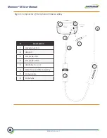
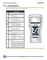
Page 10: ...ser Manual Fig 1 3 Components of the Optional Probe Assembly Description 1 Temperature Port 2 USB Port 3 Sample Gas Port 4 Sample Gas Hose 5 USB Cable Optional 6 Water Trap and Filter Assembly 7 Probe...

Page 11: ...right through a field Jump to top bottom of list Access the trending screen 6 7 Enter Key Choose highlighted item Accept value character 8 Escape Key Cancel most operations and display previous scree...

Page 12: ...temperature Secure calibration function password protected Auto power off feature with sensor purge feature Status and diagnostic menus Ambient CO User Customizations Multi language interface Auto Man...

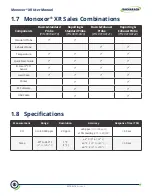
Page 13: ...Reporting Exhaust Probe P N 0019 8122 Standard Probe Exhaust Probe Temperature Quick Start Guide B Smart CO Sensor Hard Case Printer PC Software USB Cable 1 8 Specifications Measurement Range Resoluti...

Page 14: ...mart CO Sensor Electrochemical P N 0024 1795 Temperature K Type thermocouple Product Approvals and Regulatory Compliance EN50270 2015 CE Mark EMC tested in accordance with European Directive RoHS Comp...

Page 15: ...ith an integral water trap filter and is used to draw a gas sample into the analyzer from the room grilles diffusers and furnace flues 1 Inspect the flexible hose for cracks If a hose is defective rep...

Page 16: ...espectively LEFT and RIGHT arrow buttons position the active cursor on specific elements of a value to be changed LEFT arrow button displays the CO Trending screen from the Run Hold screen RIGHT arrow...

Page 17: ...Span in Hours Continuous Pump On Alkaline disposable 15 hours Lithium disposable 20 hours Rechargeable 8 hours Replace batteries as follows 1 Remove the battery cover from the back of analyzer 2 If o...

Page 18: ...0019 9376 Revision 0 18 Monoxor XR User Manual Fig 2 3 Removing the Battery Cover...

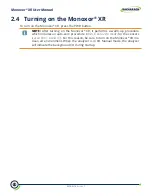
Page 19: ...turning on the Monoxor XR it performs a warm up procedure which includes an auto zero procedure when in Auto Zero mode for the sensors see section 1 8 and 3 7 For this reason be sure to turn on the Mo...

Page 20: ...hion starting from the startup screens and working sequentially through the menus and menu items 3 2 The Warm Up Sequence Menus and the items contained within them are described in a top down fashion...

Page 21: ...or presses RUN HOLD to go to the Hold screen See section 6 1 Error and Warning Messages for a list of error messages 3 3 Main Menu Display the Main Menu by pressing the F2 key Note that features and...

Page 22: ...it view instrument preference Edit view system parameters Edit view test parameters Access the Calibration Password Screen and the Calibration Menu see section 3 8 Calibration Menu Calibrate sensors A...

Page 23: ...st cycle during which a status screen is displayed It shows the starting ambient CO value the current CO value and the elapsed time into the test NOTE Press the F2 key to cancel a test in progress Aft...

Page 24: ...Manual Ambient CO cont Function The test results can be printed by pressing F1 and saved to memory with a time and date stamp by pressing F3 Press F2 to return to the menu NOTE Any over range CO value...

Page 25: ...fferential value T1 T2 will also be displayed Withtemperature 1 T1 selected positionthethermocouple in the target location and wait for the temperature reading Temp to stabilize Press the SAVE button...

Page 26: ...o tests were saved since the last time that memory was cleared A Memory Full message is displayed if you try to save test 101 To view saved data use the UP and DOWN arrow buttons to highlight the desi...

Page 27: ...etup function to set date and time Use the LEFT and RIGHT arrow buttons to select the desired field to edit Then use the UP and DOWN arrow buttons to change the values of the selected field Press ENTE...

Page 28: ...elects the size of the characters on the Run Hold screen Three options are Standard 2x and 3x Options are shown below with their respective Run Hold screens Use the UP and DOWN arrow buttons to scroll...

Page 29: ...uttons to choose a row and press ENTER to begin editing the selected row Then use the UP and DOWN arrow buttons to select the desired letter number or special character for the current text position S...

Page 30: ...option sets a time period after which the analyzer displays a calibration reminder message during warm up Calibration reminders can be set to occur never 6 8 10 12 or 15 months after the last calibra...

Page 31: ...rs Provides a list from which to select an inactivity key press timeout for automatic shutdown If no key presses occur for the time specified the Monoxor XR initiates an automatic shutdown Use the UP...

Page 32: ...NTER to enable the selected Post Purge Period PURGING SENSORS is displayed on the shutdown screen if a Post Purge Period is enabled Use the UP and DOWN arrow buttons to scroll through Post purge Perio...

Page 33: ...and DOWN arrow buttons to highlight the desired zeroing method Press ENTER to save Press ESC to quit without saving CO Auto Zero CO Manual Zero By default the Monoxor XR automatically zeroes all sens...

Page 34: ...limit is selectable from 0 to 80 000 ppm Use the Up and Down arrow buttons to scroll to the desired alarm limit value then press ENTER Note that scrolling wraps forward and backwards so pressing the d...

Page 35: ...y code in order to proceed to the calibration options The default password is 1111 Use the UP and DOWN arrow buttons to scroll through numerals 0 9 until the desired numeral is reached Press ENTER to...

Page 36: ...isplays time metrics for pump use and total operation time Displays information about the measurement sensors of the instrument Displays fresh air diagnostics similar to the display at warm up After t...

Page 37: ...User Manual 3 10 Status Menu Status Menu Function This is the device status screen which displays information about the device Some of the information displayed on this screen includes serial number...

Page 38: ...PC Interface and Fyrite User Software 49 4 1 Overview To operate the Monoxor XR you simply Turn the analyzer ON Wait for the unit to warm up Take a gas sample Before beginning your test verify the fol...

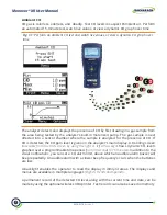
Page 39: ...rve that when power is first applied the software revision level is first displayed followed by a screen that counts down the warm up period The warm up period is 60 seconds Fig 4 1 Warm Up Screens Fo...

Page 40: ...O 0 ppm Max 3 ppm Min 0 ppm Temp 87 oF Run CO 0 ppm Max 3 ppm Min 0 ppm Temp 87 oF Sample Run Hold Screen Toggle Between Run and Hold Modes Ba ery Status Icon Print Screen to Op onal Printer Display M...

Page 41: ...periods are 30 seconds 1 minute 3 minutes 5 minutes 15 minutes Figure 4 4 CO Trending Screens The graph continues to sample CO gas while in RUN mode showing the current PPM reading above the dynamic...

Page 42: ...h is connected to the T STACK connector of the instrument After you take the two sample readings the differential value T1 T2 is calculated optionally saved in memory displayed on the main run screen...

Page 43: ...a Max CO value that represents the highest CO reading measured during the entire 15 minute test Results can be saved to memory and or printed Example Procedure for Taking Ambient CO Measurements 1 At...

Page 44: ...ng stored records is done through the MEMORY DIRECTORY MENU Press F1 to print displayed test records Example Printing Procedure Using Optional IrDA Printer 1 Monoxor XR should be turned on and display...

Page 45: ...vision 0 45 Monoxor XR User Manual Figure 4 9 Using Optional IrDA Printer IR Communication Settings Baud Rate 9600 Data Bits 8 Stop Bits 1 Parity None Protocol IRDA SIR Distance 8 16 in 20 41 cm Angle...

Page 46: ...ustom logo on printouts Logos are loaded into the instrument using the Fyrite User Software FUS Logo size is limited to 192 384 pixels height width and must be in one of the following formats BMP JPG...

Page 47: ...erface and Fyrite User Software A PC with Fyrite User Software FUS installed can set edit and transfer the following Instrument time and date Calibration password Time meters B Smart code User name In...

Page 48: ...ation Procedure 57 5 6 CO Sensor Calibration 59 5 6 1 Materials Required 59 5 6 2 CO Manual Zero Procedure 59 5 6 3 CO Sensor Span Procedure 60 5 7 T Ref Sensor Calibration 61 5 1 Serviceability The i...

Page 49: ...ged and restrict the flow of gas into the analyzer resulting in incorrect test readings NOTE An analyzer that tests natural gas furnaces normally requires less frequent cleaning than an analyzer used...

Page 50: ...carburetor cleaner into the gas sample hose and then liberally spray carburetor cleaner through the hose and out the probe tube 3 After spraying remove all the residual cleaner by repeatedly flushing...

Page 51: ...0019 9376 Revision 0 51 Monoxor XR User Manual 5 3 Filter Replacement Figure 5 1 Filter Replacement...

Page 52: ...0019 9376 Revision 0 52 Monoxor XR User Manual 5 4 CO Sensor Replacement 5 4 1 Accessing the CO Sensor Figure 5 2 Accessing the CO Sensor...

Page 53: ...out of its socket 4 Properly dispose of the old CO sensor 5 Plug new CO sensor into its socket 6 Install the CO cap by aligning it toward the open position 12 o clock as shown in the diagram below th...

Page 54: ...s entered the analyzer accepts it and returns to the CALIBRATION MENU If an incorrect code was entered the screen will display Invalid Code Check to make sure the correct code has been entered If the...

Page 55: ...connector located at the bottom of the analyzer Alternatively Plug the probe s thermocouple into the TEMP connector located at the bottom of the analyzer if using optional probe with thermocouple acce...

Page 56: ...ich the message Good Calibration should briefly appear followed by the CALIBRATE TS SPAN screen 6 Set thermocouple simulator to 572 F 300 C and then use the UP and DOWN LEFT and RIGHT arrow buttons to...

Page 57: ...re and go to the CO Sensor Span procedure that follows 1 If not already done turn ON the analyzer and display the Main Menu screen 2 Use the UP and DOWN arrow buttons to select the SETUP menu and pres...

Page 58: ...s 2 Use the UP and DOWN LEFT and RIGHT arrow buttons to enter an Applied value that exactly equals the concentration stamped on the CO cylinder NOTE Bacharach recommends using a 500 ppm calibration ga...

Page 59: ...being Low in the Warm up screen If the sensor s output is too low to be usable then the message Bad Calibration Sensor End of Life Entry Not Saved will appear 5 Close the regulator and remove the CO c...

Page 60: ...emperature sensors are measuring temperature outside the range of 4 to 212 F at warm up Make sure that the thermocouple is sampling ambient room air within the temperature range at warm up Messages wi...

Page 61: ...0024 3073 Replacement Pump Assembly 0024 1620 Battery door sensor cover 0019 9376 Instruction manual 6 3 Accessories Part Number Description 0024 1400 IrDA printer 0024 1310 Printer paper box of 5 rol...

Page 62: ...Instrument Identification A label on the back of the instrument provides the following information that is useful for service and troubleshooting manufacturer country of origin certification s part nu...

Page 63: ...rd Drive Space Android 50mb for the application only iOS 30mb for the application only 7 2 Service Centers Replacement parts and service can be obtained by contacting one of the following Bacharach Se...

Page 64: ...Bacharach Inc 621 Hunt Valley Circle New Kensington PA 15068 USA Pittsburgh PA USA Dublin IRE Stanardsville VA USA Toronto CAN www mybacharach com help mybacharach com...

Reviews: