background image

4: C

on

fig

uri

ng G

PI

O •

 48

©2016 Axia Audio- Rev 1.8.1

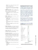
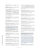
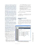
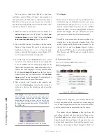
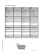
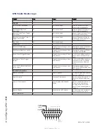
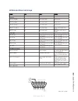
GPIO Telephone Hybrid Logic

Name

Pin

Type

Notes

INPUTS
ON Command

11

Active Low Input

Turns channel ON

OFF Command

12

Active Low Input

Turns channel OFF

PREVIEW Command

13

Active Low Input

Turns preview ON

RESET Command

14

Active Low Input

Turns channel off while not 

sending a STOP pulse

READY Command

15

Active Low Input

Illuminates OFF lamp to indi-

cate source’s readiness

OUTPUTS
ON Lamp

1

Open Collector to Logic Com-

mon Return

Illuminates when channel is 

ON

OFF Lamp

2

Open Collector to Logic Com-

mon Return

Illuminates when channel is 

OFF

PREVIEW Lamp

3

Open Collector to Logic Com-

mon Return

Illuminates when PREVIEW 

is ON

START Pulse

4

Open Collector to Logic Com-

mon Return

A 100 ms PULSE is sent when 

channel is first turned ON or 

when PVW is first selected 

(if “PVW answers” option is 

selected).

STOP Pulse

5

Open Collector to Logic Com-

mon Return

A 100 ms PULSE sent when 

channel is turned OFF.

POWER & COMMAND
Source Common

7

Logic Common

Connect to ground of source 

device or to Pin 8

Logic Common

8

Internal 5 Volt return

Can be connected to Pin 7 if 

source is not providing com-

mon

Logic + 5 Volt supply

9

Logic Supply, Individually 

Fused

Can be connected to Pin 10 

if source is not providing 

voltage; active only when 

source has been assigned to 

channel.

Source Supply

10

Common for all 5 inputs

Connect to power supply of 

source device or to Pin 9

NOT CONNECTED

6

8       7       6       5       4       3       2       1

15     14     13     12     11     10      9

ØV (GND)
SOURCE

OUTPUT

COMMON

RETURN

OUT

5

OUT

2

OUT

3

OUT

4

OUT

1

N/C

IN

5

IN

4

IN

3

IN

2

IN

1

IN

COM

+

+5 V
POWER
SOURCE

GPIO v.”ZA” 4/2009

Summary of Contents for element v.2.0

Page 1: ...element v 2 0 Installation User s Guide Includes StudioEngine and PowerStation Manual Rev v1 8 1 April 2016 p n 1490 00058 004...

Page 2: ...C electromagnetic compatibility Conformity is declared to those standards EN50081 1 EN50082 1 Important Safety Information To prevent risk of electric shock Disconnect power cord before servicing If f...

Page 3: ...dback We welcome feedback on any aspect of the Livewire products or this manual In the past many good ideas from users have made their way into software revisions or new products Please contact us wit...

Page 4: ...kinship to Bruce Wilkinson Milos Nemcik Gints Linis Michael Dosch and the rest of the Axia team in help ing to assemble this manual Kudos guys you are owed more beers than I can count c n About This...

Page 5: ...figuring GPIO 41 GPIO Port Definitions 41 GPIO Operator s Microphone Logic 42 GPIO Control Room Guest Microphone Logic 43 GPIO Studio Monitor 2 Guest Microphone Logic44 GPIO Producer s Microphone Logi...

Page 6: ...e StudioEngine Controls 119 StudioEngine Configuration Screens 119 The Main Menu 119 The Fader Channels Menu 119 The Return Monitor Inputs Menu 119 The Program Monitor Outputs Menu 120 The VMIX VMODE...

Page 7: ...and AoIP so that all types of broadcasters can excel in this ever evolving digital world Omnia Audio not only lets you stand out on the dial with your unique signature sound via legendary audio proce...

Page 8: ...Introduction viii 2016 Axia Audio Rev 1 8 1 Desk phone rings you press ignore The G M can change his own damned light bulbs...

Page 9: ...g chapters of this manual will give you an in depth understanding of the capabilities of your new Element and StudioEngine from installation to ad vanced functions This Quickstart section isn t meant...

Page 10: ...e power cords to the PSU1 receptacles on the PowerStation s rear panels and power up 5 Capture your Element control surface faders by holding the and 2 keys for 5 seconds Press when you see the CAPTUR...

Page 11: ...common TCP IP unicast IP addresses for control and web browser ac cess These are numbers you assign within the range used by your network Since most Livewire networks are not intended to be ac cessed...

Page 12: ...ortant Element is a drop in style control surface and requires a counter top cutout For cutout dimensions please refer to Appendix A Unpack the GPIO Node Power Supply that came with your Element and p...

Page 13: ...PORTANT Element s power cable is also host to all data communication between the ac tual surface and its CPU housed in the Element Power Supply GPIO Node by CANbus technol ogy it does not require a se...

Page 14: ...or indicating the Master to which this fader is now slaved a display reading 2 means that the fader is slaved to fader 2 Pressing the Options key again returns the fad er to non mirrored mode Short Na...

Page 15: ...s located in the top right corner of the module for five seconds to enter the IP Address Book Figure 1 11 To set the IP address rotate the leftmost SoftKnob to highlight the line titled Element IP Add...

Page 16: ...e Monitor Module Press and hold the star 7 4 keys simultaneously for five seconds to enter the IP Address Book Figure 1 12 To set the IP address rotate the left most SoftKnob to highlight the line tit...

Page 17: ...s are discussed in depth The next section will walk you through setting up your StudioEngine StudioEngine Quick Setup Connections Note We recommend leaving 1RU of breath ing space for ventilation abov...

Page 18: ...ndividual devices audio nodes studio controllers etc are identified by unique IP addresses But what about the audio streams these devices generate Think about how many audio sources and destinations t...

Page 19: ...h older PC systems but the trade off is that these streams have a higher amount of latency Set Your Console Type Note Manual setting of console type is only necessary on Element consoles running soft...

Page 20: ...1 Element with StudioEngine Setup Connections 10 2016 Axia Audio Rev 1 8 1 Do digital streams dream of electric DJs Just Bradbury knows...

Page 21: ...o next But before you dig in be advised that you need to assemble the rest of your Livewire network first Because so much of the configuration process depends upon hav ing access to audio sources and...

Page 22: ...ue is set at 255 255 255 0 for intranet applications A PowerStation MAIN with a PowerStation AUX will require a range of four consecutive IP addresses You will specify the first of these addresses an...

Page 23: ...vided by a PowerStation AUX solid GREEN indicates normal health If the AUX power LED is ORANGE the fault is with the PowerSta tion MAIN If a PowerStation MAIN is being used with out an AUX unit a conf...

Page 24: ...h other The failure of a power supply in either a MAIN or AUX unit will cause it to automatically and seamlessly use the backup power supplied by the remaining healthy unit Do not connect the PSU2 con...

Page 25: ...e types of Ethernet connections and it is important to use them as intended since the internal Ethernet switch is configured in a spe cific manner The types of connectors available are 100 Mbps PoE Po...

Page 26: ...n the future USB features are not currently implemented Element Console Connections PowerStation MAIN includes two connections for use in conjunction with your Element control surface PowerStation AUX...

Page 27: ...ttom simulta neously lift upward out of the shipping crate Remove packing materials and store them in the crate for future use Carefully lower Element into your counter top cut out taking care to lowe...

Page 28: ...f Element fader and accessory modules only connecting them to a powered Ethernet switch could damage the board s electronics and void your warranty Capturing Your Console If you have carefully followe...

Page 29: ...in Figure 2 12 Figure 2 12 On screen SoftKnobs Note that there are sometimes functions shown both above and below the on screen SoftKnobs When a func tion is presented above the knob turning that kno...

Page 30: ...t v2 x software supports redun dant NTP servers Use the second field in the IP Address Book to enter the address of a backup server Setting IP using the Standard Monitor Module When the PowerStation h...

Page 31: ...e Use the REBOOT soft key to begin an immedi ate reboot sequence Setting IP using the Monitor 2 Fader Module When the PowerStation has completed its start cycle meter screen appears find the numeric k...

Page 32: ...d upon re entering the IP Address book This is a security feature intended to prevent over the shoulder password theft Rotating the Action knob chooses between the fol lowing options Save stores the c...

Page 33: ...Linux to con figure your PowerStation through the HTTP interface All Axia IP addresses are assigned and managed manually This gives you complete control of your address scheme and also per mits you to...

Page 34: ...n Controls for other advanced settings Let s proceed to configure our sources Source Configuration I O Subsystem 1 Open the web browser on your computer and point it to the IP address you previously s...

Page 35: ...sabled This will preserve bandwidth plus make your setup less complicated Input Gain This setting allows you to match the level of your source so that the levels of the Livewire streams are stan dardi...

Page 36: ...ay wish to follow the convention of using the last octet as a base for your Livewire chan nel numbers For example if the Element IP address is 192 168 0 100 you may use 10001 through 10018 for the Liv...

Page 37: ...ther places where we use desti nations and they are not associated with a physical out put The setup of the PowerStation destinations is very similar to an Axia 8x8 node The configuration page for Des...

Page 38: ...s designed to operate at our nomi nal system level of 4 dBv This setting allows to you trim the output level 12 dB to ensure that you are feeding your external equipment with the correct signal level...

Page 39: ...and tedious parts of studio building has always been tying data to audio sources Consider the wiring of line selector modules you need a cable for the remote audio source a set of wires for a start cl...

Page 40: ...mined for your network Different operating systems use differ ent methods to do this please consult your OS s docu mentation for specific instructions Source Profile Options 1 Enter the IP address of...

Page 41: ...e you typed into the Source Profile Name field above Choose Allow Application to Override if you d like the PAD text displayed instead Choose Show Both to have the Source Name and PAD text alternately...

Page 42: ...It can have an individual headphone feed Studio Guest is used for any mic located in a separate studio Its logic mutes the Studio moni tors when On It can have an individual head phone feed Line is us...

Page 43: ...annel ON will cancel its Preview assignment Preview ON turns Channel OFF Does just what it says sometimes used for Phone channels HYBRID ANSWER MODE This setting allows you to tailor Element s Hybrid...

Page 44: ...he Program 1 bus minus the source when this source s fader is ON and feeds the Phone bus minus the source when the fader is OFF The Phone bus is actually a special variant of PGM4 The Phone bus is pre...

Page 45: ...ngs AUTO START TIMER Determines whether the event timer found in Element s right hand meter display will reset to zero when this source s fader is turned on Disabled timer will not reset when this sou...

Page 46: ...Adjustment range is between 0dB and 30 dB COMPRESSOR THRESHOLD De termines the point at which the Compressor will op erate if set to Active Adjustment range is between 0dB and 30dB COMPRESSOR THRESHO...

Page 47: ...ts De Essing is just what you think it is a way to electronically remove extra sibi lance from your mic channel If your mic is particularly sensitive to s and th sounds and accentuates them on air De...

Page 48: ...omagic If the hybrid source is loaded to an Engine and the engine is generating a mix minus source already the list box will show TWO iden tical channels for the source but one will have a description...

Page 49: ...urce Also take another look at the GPIO screen on your browser Note the green indicators that have appeared on the port representing your hybrid switch the Element channel on and off and you ll observ...

Page 50: ...3 Configuring Inputs 40 2016 Axia Audio Rev 1 8 1 CAT 6 small and light yet sound and data pour forth What magic is this...

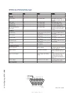
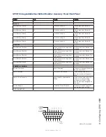
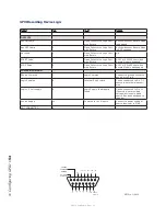
Page 51: ...that when rack mounting these units you leave at least 1RU of space above and below to ensure adequate ventila tion GPIO Port Definitions Each Axia GPIO device has either four or eight DB 15 connecto...

Page 52: ...TALK to Monitor 2 Lamp 3 Open Collector to Logic Com mon Return Illuminates when TALK TO MON2 is active MUTE Lamp 4 Open Collector to Logic Com mon Return Illuminates when MUTE is active TALK to PREV...

Page 53: ...llector to Logic Com mon Return Illuminates when TALK is active MUTE Lamp 4 Open Collector to Logic Com mon Return Illuminates when MUTE is active TALK to SOURCE Lamp 5 Open Collector to Logic Com mon...

Page 54: ...Collector to Logic Com mon Return Illuminates when TALK is active MUTE Lamp 4 Open Collector to Logic Com mon Return Illuminates when MUTE is active TALK to SOURCE Lamp 5 Open Collector to Logic Com m...

Page 55: ...TALK to MONITOR 2 Lamp 3 Open Collector to Logic Com mon Return Illuminates when TALK to MON2 is active MUTE Lamp 4 Open Collector to Logic Com mon Return Illuminates when MUTE is active TALK to PREVI...

Page 56: ...nates when PREVIEW is ON START Pulse 4 Open Collector to Logic Com mon Return A 100 msec pulse when the channel status changes from OFF to ON STOP Pulse 5 Open Collector to Logic Com mon Return A 100...

Page 57: ...Logic Com mon Return Illuminates when TALK is active MUTE Lamp 4 Open Collector to Logic Com mon Return Illuminates when MUTE is active TALK to SOURCE Lamp 5 Open Collector to Logic Com mon Return Ill...

Page 58: ...pen Collector to Logic Com mon Return A 100 ms PULSE is sent when channel is first turned ON or when PVW is first selected if PVW answers option is selected STOP Pulse 5 Open Collector to Logic Com mo...

Page 59: ...Com mon Return Illuminates when PREVIEW is active TALK TO EXT Lamp Element 4 Open Collector to Logic Com mon Return Illuminates when Talk to External is active TALK to CR Active Lamp 5 Open Collector...

Page 60: ...ollector to Logic Com mon Return A 100 ms PULSE sent when event timer is started from zero Countdown Timer Trigger Output 4 Open Collector to Logic Com mon Return A 100 ms PULSE sent when countdown ti...

Page 61: ...Com mon Return Illuminates when PREVIEW is ON START Pulse 4 Open Collector to Logic Com mon Return A 100 ms PULSE sent when channel is first turned ON STOP Pulse 5 Open Collector to Logic Com mon Retu...

Page 62: ...tch 3 Open Collector to Logic Com mon Return Active when PAUSE button is depressed ENGAGE Switch 4 Open Collector to Logic Com mon Return Active when ENGAGE button is depressed Not Used 5 Open Collect...

Page 63: ...tch 3 Open Collector to Logic Com mon Return Active when User Button 3 is pushed User Button 4 Switch 4 Open Collector to Logic Com mon Return Active when User Button 4 is pushed User Button5 Switch 5...

Page 64: ...Return A 100 mS PULSE sent when Record Mode is disengaged POWER COMMON Source Common 7 Logic Common Connect to ground of source device or to Pin 8 Logic Common 8 Internal 5 Volt return Can be connect...

Page 65: ...turn A 100 mS PULSE sent when Timer is reset FREEZE Pulse 4 Open Collector to Logic Com mon Return A 100 mS PULSE sent when Timer is frozen Not used 5 Open Collector to Logic Com mon Return POWER COMM...

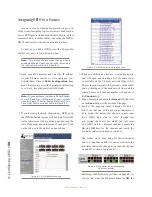
Page 66: ...e showing the state of the input and output pins of each port Click on the list icon to the right of an unused line 3 When you click on any list icon a small popup win dow will open enumerating all of...

Page 67: ...cally configures the port for the type of device supplying the audio and send the appropriate logic commands to that port when the source is assigned to a Element channel A word about the GPIO Ports I...

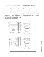
Page 68: ...und through the output transistor The volt age drop between the collector and emitter may not be low enough to activate the device so an external relay controlled by the GPO may need to be used to pro...

Page 69: ...t does not in clude built in meters or other displays Instead Element GPIO Power Supply Node provides a VGA output to feed your choice of display monitors If you are using the PowerStation the video i...

Page 70: ...there are installed faders each with its own automated mix minus feed Got 24 faders You can have 24 mix minuses GPIO Chapter 4 explained how sources can have associat ed GPIO General Purpose Input Ou...

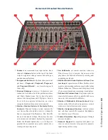
Page 71: ...s keys a set of keys are provided for convenient on console control of ex ternal profanity delay units 5 Six SoftKnobs are context sensitive when any Direct Access key is pressed the on screen dis pla...

Page 72: ...shows the function affected by rotating and or pushing each knob 6 Record Mode and Load Profile Keys let opera tors recall customized Show Profiles and activate Record Mode to quickly capture off air...

Page 73: ...nction bus but can optionally be slaved to meter whatever source is auditioned in the Control Room Monitors 7 Annunciator Panel informs operators when Mic channels are open when audio is being auditio...

Page 74: ...ickly toggle through sources available to any particular fader by holding the Options key and pressing the OFF key Each time the OFF key is pressed the fader will take the next source from that fader...

Page 75: ...a source with a backfeed and while hold ing it press the Preview button both will latch on making it easy to have a hands free off line chat using the CR Mic Pushing either one clears both Fader The...

Page 76: ...drop Making Calls To dial out from the console press any con trol key Off On Hold Set or Preview on a fader that hosts a Phone source This assigns the Keypad on the Monitor Module to that fader Di ali...

Page 77: ...4 Phone Module in the previous section For details on hybrid control operation and descrip tion of Status Symbols used please refer to the Opera tor s Manual supplied with your Telos phone system Tip...

Page 78: ...SEND A B C D These controls allow you to send the output of the ac tive fader to any or all of the four Aux Send buses for outboard audio effects processing custom IFB mix es etc Each Aux Send contro...

Page 79: ...hen become active With the 2 fader monitor module the various Chan nel Options are selected by navigation with the Soft Knobs Channel Jumping If any fader is in Op tions mode you can quick jump to set...

Page 80: ...onitor Module useful for integration with hybrids that support these features ChannelOptions Pressing the Channel Options keys above your faders will generate a slightly different display if you have...

Page 81: ...ion displayed differs based on the type of source currently assigned to the active fader Shown clockwise from top left Line Source Channel Options screen Mic Source Channel Options screen Phone Source...

Page 82: ...tatus If the source is not in use anywhere else the operator is informed that they have Full Con trol of the source as shown in the left hand box above and backfeed and logic operate nor mally Source...

Page 83: ...amics screen Standard Monitor Module only Note High Mid and Low band adjustments provide up to 25 dB of cut and 15 dB of boost Element EQ features SmartQ automatic band width system that varies the Q...

Page 84: ...io is absent Freeze would be the default since it almost always improves results De Essing is just what you think it is a way to electronically remove extra sibilance from your mic channel If your mic...

Page 85: ...le only This control changes the other control operates Pan Mode or Phase Pressing this knob will exit the Pan Mode Menu screen Pan Balance Rotating this SoftKnob adjusts the Pan setting for mono sour...

Page 86: ...in adjusted by the fader fixed level On Post sends the source assigned to the fad er to the selected Aux Send bus after having its gain adjusted by the fader variable level Off sends no audio to the A...

Page 87: ...anity delay unit using one of Element s GPIO ports Please refer to Chapter 4 Configuring GPIO for instructions on GPIO setup The keys provide for remote activation of Dump Exit Pause and Engage functi...

Page 88: ...Talk To Monitor 2 Key The board operator can push and hold this key to talk to the talent listening to the Monitor 2 feed While the key is depressed audio from the Control Room mic channel is fed pre...

Page 89: ...reload the currently active profile resetting the board to a nominal state if they wish to return to their normal configuration after making on the fly changes Select Take Rotate this knob to scroll t...

Page 90: ...ne source selector When the operator pushes the Preview knob the Head phone Source menu is displayed Voila The H P PROC knob allows the board op to turn Headphone Processing on and off define how it o...

Page 91: ...adphone channel only Program audio is still present in the right channel of the operator s headphones After making a selection push the knob to Take the new value MONITOR MODE knob Rotate to select fr...

Page 92: ...and AUX RETURNS Figure 5 18 2 Fader Meter Options menu screen Meter Ballistics permits the selection of various international metering standards Those selections are meter options are Full Scale VU El...

Page 93: ...review is enabled in headphones Element s Aux buses can be used as utility buses for mixing for constructing custom IFB mixes or as effects buses for production Pressing the Sends Returns key once tak...

Page 94: ...lect either of the Aux Return mixes for au ditioning in the Preview channel the on screen menu indicates which Aux Send is selected Push the knob to preview release it to end the preview Figure 5 22 A...

Page 95: ...Reset knob to set the new time you ve dialed in Press the Start Stop knob to begin or end the countdown Pressing Freeze holds the on screen Timer display so you may take note of it the timer continue...

Page 96: ...s to PGM 4 Record which is indicated by flashing the PGM 4 indicator Pressing the Record Mode key a second time deac tivates Record Mode and stops the recorder via GPIO Help Key and Magic Key Sequence...

Page 97: ...Producer s microphone is meant to be used at a position within the Control Room where a morning show or talk show producer would normally sit This mic type mimics the operation of the Control Room mi...

Page 98: ...ivately using the Talkback function Line Channel Operation Line level devices like CD players tape players etc use the Line Channel profile The Line Channel is ste reo but the user can change the inpu...

Page 99: ...g the Talkback bus When Talk is acti vated all outputs for that channel are muted and the source audio is fed to the Talkback bus the channel s Talkback key lights and its Status Symbol displays T Whe...

Page 100: ...5 Element Operations 90 2016 Axia Audio Rev 1 8 1 Capital budget may you never decrease for we need new test gear...

Page 101: ...ofile using Show Profiles key located on Element s Master Module to make sure you re in ready mode The first step in building a Show Profile is to set up Element using the Channel Options Monitor Opti...

Page 102: ...er there may be a few more options you d like to tweak some options not accessible from Element itself Let s go a little deeper into Show Profiles to find out exactly what s available to you Suggestio...

Page 103: ...ion SOURCE ID The name of the source you assigned to this fader You can change the source using the drop down box FEED TO SOURCE MODE Specify PGM 1 2 3 4 AUX SEND A B C D or AUTO mix minus for this so...

Page 104: ...or Retain Source Settings NOISE GATE DEPTH Sets the amount of noise reduction that will be applied to the mic audio if the noise gate is set to Active and the Noise Gate Threshold is reached Adjustme...

Page 105: ...ined position when a Show Profile is loaded Choose Off to specify a setting of Use to specify a level to use from 73 dB to 10 dB or Retain Existing Setting which will cause the motor fader to make no...

Page 106: ...Re turn bus Select Use and enter a gain value between 25 dB and 10 db to trim overall return gain if desired or select Retain Existing Setting Aux Return A B On Off Status Choose Off to turn the sele...

Page 107: ...le faders to Preview by pushing and holding any lit Preview key while pushing other Preview keys to add or subtract If Disable is chosen each Preview key works like a press on press off latching switc...

Page 108: ...or the six extra meters that can optionally be dis played in the centre section of the Element display The selections for each of the six meters are extensive and include all Program Aux External Moni...

Page 109: ...ro file to be loaded with nothing assigned to the board op s headphones CR HEADPHONES MASTER GAIN Allows you to Use as much as 85 dB of gain reduction on the au dio signal sent to the Control Room hea...

Page 110: ...ternal is chosen from the Studio 2 monitor assignment list STUDIO MONITOR MASTER GAIN Allows you to Use as much as 85 dB of gain reduction on the audio signal sent to the Monitor 2 Speakers You can al...

Page 111: ...es you back to Show Profile Settings without saving changes Record Mode Screen Element s Record Mode helps tal ent quickly prepare to record a phone bit interview or other program segment for later ai...

Page 112: ...ation Note that making a change in this screen also chang es the value of the Group Start setting in the fader s Channel Options screen described previously in this chapter and vice versa Phone Screen...

Page 113: ...e Livewire destinations would be con nected to the mixer inputs and your mixer outputs would be connected to node inputs Your VMIX is wired in a very similar manner Constructing Virtual Mixes with VMI...

Page 114: ...num ber assigned to it is a unique channel number just as you would in configuring the channel numbers assigned to Audio Node streams When enabled you can use this source anywhere in your network In m...

Page 115: ...from anAudio Node and each mix and monitor feed from a StudioEngine must have a unique channel number so do each of the VMIX sources that you want to make available to the network In most cases only t...

Page 116: ...select GPIO triggers time based events user button pushes serial port commands and other options and combinations of options to decide when to make changes to any fader in a VMIXER The user can make...

Page 117: ...the console is in Sur round 5 1 2 mixing mode Status and Audio indicate the health of each par ticular channel Status indicates OK to inform you that a stream is working normally Audio shows a colore...

Page 118: ...channel Combine R L Right channel of first VMIX in put is sent to Left output channel and Left chan nel of second VMIX input is sent to Right output channel Combine R R Right channel of first VMIX in...

Page 119: ...to one channel of the stereo Record bus You d like to use this split recording for an interview with a host several guests placing the host on the Left channel and all the other sources guest mics ph...

Page 120: ...7 Virtual Mixer 110 2016 Axia Audio Rev 1 8 1 The cup steams sweet scent wafting lightly in the air Mmmmm it is Earl Grey...

Page 121: ...ation Advanced Settings for StudioEngine are found in Chapter 9 and PowerStation settings in Chapter 10 Element Configuration Screens The Element Control Center Figures 8 1 and 8 2 show the first scre...

Page 122: ...lds Why would you want to do this Well you could simplify NTP access by entering the server s name tmc edu instead of 128 249 1 1 Or if you set up a DNS server in house you could give real names to yo...

Page 123: ...ement operator display To do so create a PNG file in Photoshop or any similar image editor This file must measure a maximum of 129 x 97 pixels to fill the allocated display area Use the Browse and Upl...

Page 124: ...es a shot of the Element s Operator screen This in combi nation with the activity log can be used to determine just what the operator is seeing useful for at home troubleshooting during those 6 AM Sun...

Page 125: ...see two lines one red and one blue These lines provide a graphical representation of the CANBus transmit and receive data You will see a momentary spike only when a button is pressed on the console or...

Page 126: ...guring GPIO Note that the GPIO section of the PowerStation is not associated with the Element but rather with the MAIN and AUX I O sub systems Script Information Menu Element consoles use standard Jav...

Page 127: ...to the Profiles submenus Show Profiles and Source Profiles Menus These menus allow you to construct and administer Show and Source Profiles specific to this Element con sole Refer to Chapter 3 Workin...

Page 128: ...8 Advanced Element Controls 118 2016 Axia Audio Rev 1 8 1 Featureless paper this page would have been empty save for this haiku...

Page 129: ...purely informational in nature Others Options System contain options and settings that are used for setup of your StudioEngine The Fader Channels Menu Settings shown here are not adjustable Useful fo...

Page 130: ...feed the Control Room mon itors CR Headphones Contains whatever audio source your operator has selected to feed the Control Room headphones Preview The feed to the Preview Cue speaker Talk to CR This...

Page 131: ...make ad justments to the Element Virtual Mixer system Please see Chapter 7 Virtual Mixer for details on how to use VMIX and VMODE The Intercom Menu This screen will be active if there is an Intercom...

Page 132: ...sed to interact with the Intercom system More information on this topic is covered in the IP Intercom manual These virtual GPIO ports are accessible through port 4013 If you need to configure GPIO rou...

Page 133: ...t all active au dio streams in and out of the StudioEngine This is useful primarily for diagnostics and contains no settings that can be modified Axia tech support may ask you to report information re...

Page 134: ...you to set the detail level of the log files that are saved internally in the StudioEngine There are four settings ranging from Disabled to Detailed Two other sections permit you to download a diag no...

Page 135: ...ioEngine By default the user name is user and there is no password The Hardware and Firmware section is where you upload and apply new operating software for the StudioEngine Use the File field and th...

Page 136: ...9 StudioEngine Controls 126 2016 Axia Audio Rev 1 8 1 Meters dance in time Waveforms swirl around my skull Music looks so cool...

Page 137: ...ly speaking a PowerStation MAIN is re ally three separate devices with three IP addresses The home page shown in Figure 10 1 will link you to all three devices plus the PowerStation AUX if one exists...

Page 138: ...2 168 0 120 In this case the PowerStation s Ethernet switch would be auto matically assigned 192 168 0 121 I O Subsys tem MAIN will be 192 168 0 122 and I O Sub system AUX will be 192 168 0 123 Netmas...

Page 139: ...name you ve defined for this PowerStation for con firmation should you be viewing the page remotely Program and Monitor Out This is where you enable and assign unique channel numbers to all of your Po...

Page 140: ...e regular Program 1 out puts that are feeding your transmitter You will have other processing equipment for that purpose To apply choose one from the drop down box and choose Apply V Mixer and V Mode...

Page 141: ...escribed at the beginning of this section System The System Menu of the PowerStation s MixEngine displays some different information than a stand alone StudioEngine however the functionality is identi...

Page 142: ...ton takes the software in Bank 1 and loads it into Bank 0 which opens Bank 1 for new software You can run PowerStation software from either Bank 0 or Bank 1 Simply click on the radio but ton next to t...

Page 143: ...adroom you have at your audio inputs and outputs The Green indicator is considered safe The meter bar will change to Yellow at 20 dB below full scale and it will change to Red at 10 dB below full scal...

Page 144: ...ion for two differ ent versions of firmware The IO Subsystem will reboot when the version is changed Quality of Service QoS The QoS page has advanced settings related to the levels for quality of serv...

Page 145: ...STPport fast may optionally be used when you connect up to four PowerStations in a ring configuration By selecting this mode the normal STP logic is reversed The port is allowed to start sending packe...

Page 146: ...wn Be aware that making changes to device pass words after your PathfinderPC server has been configured is going to make your life more com plicated We encourage you to make password changes at the be...

Page 147: ...tput Crosstalk Isolation Stereo Separation and CMRR Analog Line channel to channel isolation 90 dB isolation minimum 20 Hz to 20 kH Microphone channel to channel isolation 80 dB isolation minimum 20 H...

Page 148: ...tor 2 Stereo Studio monitor speakers source and level controlled by Element Monitor 2 con trol Studio Headphone Talent Stereo Studio talent headphones source same as main xed level output with talkbac...

Page 149: ...Appendix A Specifications 139 2016 Axia Audio Rev 1 8 1...

Page 150: ...Appendix A Specifications 140 2016 Axia Audio Rev 1 8 1 Dark dark as coal tar it pours out bitter and strong That s Starbucks for you...

Page 151: ...voltage directive 89 336 EEC electromagnetic compatibility Application of Council Directives 93 68 EEC CE Marking 73 23 EEC safety low voltage directive 89 336 EEC electromagnetic compatibility Stand...

Page 152: ...unity 3 1 Standards Applied 3 1 1 ESD Susceptibility Measurement Document IEC 1000 4 2 IEC 801 2 Immunity to static electricity 3 1 2 Radiated Susceptibility HF Electric Field Document IEC 1000 4 3 IE...

Page 153: ...ge Not Found error when I try to connect to Element using my Web browser What s wrong It s possible that your computer s network configu ration needs adjustment Livewire networks do not assign IP addr...

Page 154: ...gs often requires a reboot before those settings take effect Once your computer is using the same IP network address and subnet as your Element you should be able to access your Element s web page If...

Page 155: ...es for other non video related problems on screen if at all possible If the BIOS cannot initiate the display adapter is issues the POST code for a display error which must be corrected before any othe...

Page 156: ...panel If your new module has an accompanying overbridge display you will need to remove one of Element s end panels in order to insert it Ascertain which end panel is closest to the position your new...

Page 157: ...panel are in use you can connect a new module to the unused jack on any other module Connect the other end of the patch cable to the RHJ45 connector located on the bottom of your new module connect th...

Page 158: ...instructed to turn each one off This serves as a combination lamp and switch test When the lamp switch test is complete you ll be prompted to perform a fader operation test As you move the faders on...

Page 159: ...by pulling gently upward 6 Using the 1 16 hex wrench remove the two hex screws at the top and bottom of the fader slot The fader will drop out from the bottom of the module 7 Lay the fader assembly o...

Page 160: ...The Fader 1 Snap the cover onto the fader body 2 From below reinsert the fader into position in the surface taking care that the end marked is in stalled adjacent to the channel s On Off keys 3 Reinst...

Page 161: ...ne system If you have not yet configured your VX system please refer to the Telos VX User Manual to do so before proceeding You will need to know the following things in order to configure Element for...

Page 162: ...on Phone In the Phone URL field enter the IP ad dress of your VX In the screenshot above a VX IP address is shown as vx 192 168 0 9 where 192 168 0 9 is the IP of a VX Engine You can also specify a u...

Page 163: ...e Hybrid give it an Element source name such as VX Hybrid1 and select Phone for Source Type The Source Profile for the hybrid should be filled in as follows Leave the Phone hybrid IP field empty Leave...

Page 164: ...ns and Feed To Source Mode op tions documented elsewhere in the manual Activate configuration When you are done entering configuration save your Show and Source profiles and load one of your newly edi...

Page 165: ...s telos and the IP address follows like so ap telos 192 168 100 106 2 Configure the Show In the same screen where you entered the IP address of your Telos phone system enter the Telos Show running on...

Page 166: ...nel emulating a dedicated hybrid Normally this is used with a 4 Fader Module The other fields in the Source Profile page are non phone specific and may be configured as you wish Re peat this procedure...

Page 167: ...ller 2 Phone Fader Module Status Symbol indicates backfeed mix minus to hybrid is active Transfer key Block All key Line selection keys Hybrid 1 Line selection keys Hybrid 2 Hold key Hybrid 1 Hold key...

Page 168: ...when they at tempt to call in Lines that are active i e on air and on Hold are not affected by the Block All key however if these lines are dropped while Nx12 or TWOx12 is in Busy mode these lines wi...

Page 169: ...ither manually or auto matically using Show Profiles Pressing the fader channel On button answers a ring ing in call or selects an inactive line for an outgoing call Pressing Preview has the same effe...

Page 170: ...GPIO as well as to audio signals Element will generate the appropriate control signals for hybrids when Phone is selected as the source type The status display above the entry boxes show you the GPIO...

Page 171: ...choose the Primary Source that you entered in the audio node s setup page Give it an Element source name and se lect Phone for source type Set the default input mode to Left Operation Load the hybrid...

Page 172: ...Appendix D Working With Hybrids 162 2016 Axia Audio Rev 1 8 1 Mimicking nature streams combine to form anew many become one...

Page 173: ...ble at https www telosalliance com Axia Pre installation Hardware Check Before installing your new panel we need to perform a quick hardware check Open the overbridge panel on your Element and ex amin...

Page 174: ...Control accessory panel to the GPIO port of your Element Power Supply It assumes you have already made the cable con The bracketed numbers refer to device type and ID number respectively The first di...

Page 175: ...an Axia GPIO Node It assumes you have already made the cable connection described above in Installation Using a PC connected to the Axia network enter the configuration page for the GPIO Node to which...

Page 176: ...Appendix E Accessory User Panels 166 2016 Axia Audio Rev 1 8 1 Meeting coffee black Less Powerpoint I beg you Must keep eyes open...

Page 177: ...ddress automatically from a pool Because Livewire devices are permanently attached and because it is more desirable to know the IP address attached to a particular node and perhaps assign them in some...

Page 178: ...Appendix F Worksheets 168 2016 Axia Audio Rev 1 8 1 Axia IP Address Assignment Worksheet IP Address Device Name Location Notes...

Page 179: ...Appendix F Worksheets 169 2016 Axia Audio Rev 1 8 1 Axia Audio Channel Assignment Worksheet SOURCES Channel ID Number Device Name Device Location Notes...

Page 180: ...Appendix F Worksheets 170 2016 Axia Audio Rev 1 8 1 Axia Audio Channel Assignment Worksheet DESTINATIONS Channel ID Number Device Name Device Location Notes...

Page 181: ...the use of an uninterruptible power supply UPS with all of our Products Telos products are to be used with registered protective interface devices which satisfy regulatory requirements in their count...

Page 182: ...t to and from the end user s location Telos will then in its sole discretion repair or replace the warranted Product at Telos expense Telos also reserves the right if it is not economically justifiabl...

Page 183: ...Warranty 173 2016 Axia Audio Rev 1 8 1 TCP IP How did we live without thee Analogicly...

Page 184: ...THIS PAGE INTENTIONALLY LEFT BLANK...

Page 185: ...THIS PAGE INTENTIONALLY LEFT BLANK...

Page 186: ...Axia Audio a Telos Alliance Company 1241 Superior Ave Cleveland Ohio 44114 USA 1 216 241 7225 TelosAlliance com 2016 TLS Corp Axia The Telos Alliance All Rights Reserved G16 15023...

Reviews: