


3
In the Power Dimensioning dialog box, click OK.
4
Press
ENTER
twice to exit the command.
NOTE
Parametric dimensions and reference dimensions are shown in different
colors.
To create a radial reference dimension
1
Start the power dimensioning command. On the command line, enter
AMPOWERDIM
.
2
Respond to the prompts as follows:
Specify first extension line origin or
[Linear/Angular/Radial/Baseline/ Chain/Options/Update] <select
object>:
Press
ENTER
Select arc, circle, line or dimension:
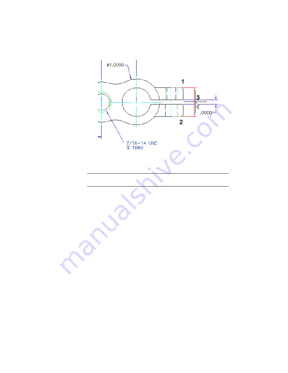
In the base view, click the circle indicating the hole (1), drag the dimension to
a placement point (2) and click
376 | Chapter 19 Using Autodesk Inventor Link Support
Summary of Contents for 057A1-09A111-1001 - AutoCAD LT 2009
Page 1: ...AutoCAD Mechanical 2009 User s Guide January 2008 ...
Page 10: ...2 ...
Page 50: ...42 ...
Page 58: ...50 ...
Page 106: ...98 ...
Page 157: ...This is the end of this tutorial chapter Inserting Fits Lists 149 ...
Page 158: ...150 ...
Page 174: ...166 ...
Page 179: ...3 In the Select a Screw dialog box select Socket Head Types Inserting Screw Connections 171 ...
Page 180: ...4 Select ISO 4762 and Front View 172 Chapter 9 Working with Standard Parts ...
Page 188: ...4 Select ISO 10642 and Front View 180 Chapter 9 Working with Standard Parts ...
Page 212: ...204 ...
Page 229: ...6 In the Set Value dialog box specify Column Material Value 8 Creating Parts Lists 221 ...
Page 263: ...Save your file This is the end of this tutorial chapter Inserting Bearings 255 ...
Page 264: ...256 ...
Page 266: ...258 ...
Page 282: ...274 ...
Page 292: ...284 ...
Page 306: ...298 ...
Page 348: ...340 ...
Page 368: ...360 ...
Page 406: ...398 ...
Page 414: ......