


Creating Side Views of Shafts
Insert a side view of the shaft.
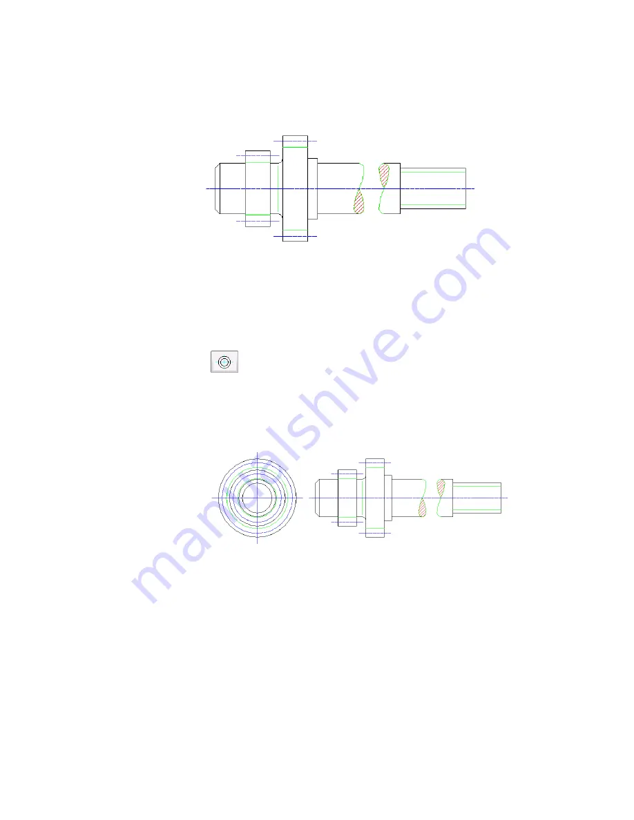
To insert a side view
1
Click the Side view button.
2
In the Side view from dialog box, select Right. Click OK.
3
Respond to the prompt as follows:
Specify insertion point:
Press
ENTER
The right side view is inserted at the proposed position.
In the mechanical browser, the new right side view is listed within the
shaft component along with the existing front view. The right side view
includes its hide situations.
Creating Side Views of Shafts | 247
Summary of Contents for 057A1-09A111-1001 - AutoCAD LT 2009
Page 1: ...AutoCAD Mechanical 2009 User s Guide January 2008 ...
Page 10: ...2 ...
Page 50: ...42 ...
Page 58: ...50 ...
Page 106: ...98 ...
Page 157: ...This is the end of this tutorial chapter Inserting Fits Lists 149 ...
Page 158: ...150 ...
Page 174: ...166 ...
Page 179: ...3 In the Select a Screw dialog box select Socket Head Types Inserting Screw Connections 171 ...
Page 180: ...4 Select ISO 4762 and Front View 172 Chapter 9 Working with Standard Parts ...
Page 188: ...4 Select ISO 10642 and Front View 180 Chapter 9 Working with Standard Parts ...
Page 212: ...204 ...
Page 229: ...6 In the Set Value dialog box specify Column Material Value 8 Creating Parts Lists 221 ...
Page 263: ...Save your file This is the end of this tutorial chapter Inserting Bearings 255 ...
Page 264: ...256 ...
Page 266: ...258 ...
Page 282: ...274 ...
Page 292: ...284 ...
Page 306: ...298 ...
Page 348: ...340 ...
Page 368: ...360 ...
Page 406: ...398 ...
Page 414: ......