


Click Finish.
10
In the Create Hide Situation dialog box, click OK.
A hide situation is created, and is listed in the mechanical browser.
The sprocket is inserted into the drawing.
Create the next sprocket.
11
Start the Draw Sprocket/Pulley command again. On the command line,
enter
AMSPROCKET
and press
ENTER
.
12
In the Select Pulley and Sprocket dialog box, Details panel, click Sprockets
➤
Front view.
Respond to the prompts:
Specify insertion point:
Select the center of circle c
Specify rotation angle < 0 >:
Enter
360
, press
ENTER
13
In the Sprockets - Size Selection dialog box, select ISO 606 05B-1, and
then click Next.
14
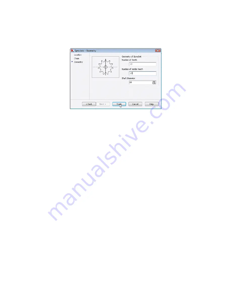
In the Sprockets - Geometry dialog box, specify:
Geometry of Sprocket:
Number of teeth:
51
Number of Visible Teeth:
3
Shaft Diameter:
10
294 | Chapter 14 Calculating Chains
Summary of Contents for 057A1-09A111-1001 - AutoCAD LT 2009
Page 1: ...AutoCAD Mechanical 2009 User s Guide January 2008 ...
Page 10: ...2 ...
Page 50: ...42 ...
Page 58: ...50 ...
Page 106: ...98 ...
Page 157: ...This is the end of this tutorial chapter Inserting Fits Lists 149 ...
Page 158: ...150 ...
Page 174: ...166 ...
Page 179: ...3 In the Select a Screw dialog box select Socket Head Types Inserting Screw Connections 171 ...
Page 180: ...4 Select ISO 4762 and Front View 172 Chapter 9 Working with Standard Parts ...
Page 188: ...4 Select ISO 10642 and Front View 180 Chapter 9 Working with Standard Parts ...
Page 212: ...204 ...
Page 229: ...6 In the Set Value dialog box specify Column Material Value 8 Creating Parts Lists 221 ...
Page 263: ...Save your file This is the end of this tutorial chapter Inserting Bearings 255 ...
Page 264: ...256 ...
Page 266: ...258 ...
Page 282: ...274 ...
Page 292: ...284 ...
Page 306: ...298 ...
Page 348: ...340 ...
Page 368: ...360 ...
Page 406: ...398 ...
Page 414: ......