Define the enlargement area for the detail ...
Center of circle or [Rectangle/Object]:
Select the center of the detail
(3)
Specify radius or [Diameter]:
Drag the radius to the desired size (4)
3
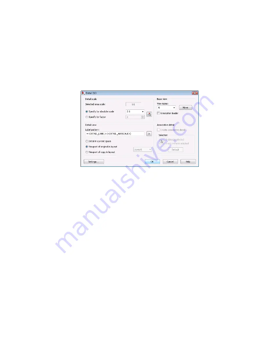
In the Detail dialog box, specify the settings shown in the illustration.
Click OK.
4
Respond to the prompt as follows:
Select target position (<Return> for current position):
Place the detail to the right of the current viewport
124 | Chapter 6 Working with Model Space and Layouts
Summary of Contents for 057A1-09A111-1001 - AutoCAD LT 2009
Page 1: ...AutoCAD Mechanical 2009 User s Guide January 2008 ...
Page 10: ...2 ...
Page 50: ...42 ...
Page 58: ...50 ...
Page 106: ...98 ...
Page 157: ...This is the end of this tutorial chapter Inserting Fits Lists 149 ...
Page 158: ...150 ...
Page 174: ...166 ...
Page 179: ...3 In the Select a Screw dialog box select Socket Head Types Inserting Screw Connections 171 ...
Page 180: ...4 Select ISO 4762 and Front View 172 Chapter 9 Working with Standard Parts ...
Page 188: ...4 Select ISO 10642 and Front View 180 Chapter 9 Working with Standard Parts ...
Page 212: ...204 ...
Page 229: ...6 In the Set Value dialog box specify Column Material Value 8 Creating Parts Lists 221 ...
Page 263: ...Save your file This is the end of this tutorial chapter Inserting Bearings 255 ...
Page 264: ...256 ...
Page 266: ...258 ...
Page 282: ...274 ...
Page 292: ...284 ...
Page 306: ...298 ...
Page 348: ...340 ...
Page 368: ...360 ...
Page 406: ...398 ...
Page 414: ......


