


2-2
Chapter 2: Hardware information
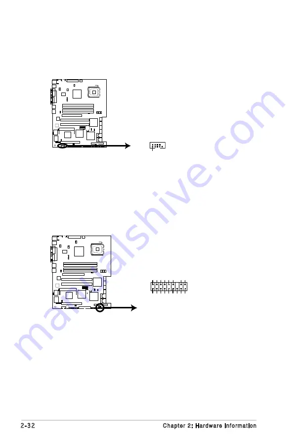
6.
Serial port connector (10-1 pin COM2)
This connector is for a serial (COM) port. Connect the serial port module
cable to this connector, then install the module to a slot opening at the back
of the system chassis. The serial port module is purchased separately.
7.
SAS LSI1068 ports LED connector (18-1 pin SASLED1)
(
For P5M2/SAS model only
)
This connector is for SAS link state’s LED. The active LOW Fault LED signals
are nominally configured to indicate a SAS link fault for each respective phy.
The active LOW Activity LED signals are nominally configured to indicate
SAS link activity.
P5M2/SAS
®
P5M2/SAS SAS LED Connector
SASL ED1
ACT
_LED0
ACT
_LED1
ACT
_LED2
ACT
_LED3
ACT
_LED4
ACT
_LED5
ACT
_LED6
ACT
_LED7
FL
T_
L
ED0
FL
T_
L
ED1
FL
T_
L
ED2
FL
T_
L
ED3
HB_LE
D
FL
T_
L
ED4
FL
T_
L
ED5
FL
T_
L
ED6
FL
T_
L
ED7
P5M2 Series
®
P5M2 Series COM Port Connector
PIN 1
COM 2
Summary of Contents for P5M2
Page 1: ...Motherboard P5M2 Series P5M2 P5M2 SAS ...
Page 14: ...xiv ...
Page 26: ...2 Chapter 2 Hardware information 2 2 3 Motherboard layout P5M2 Layout ...
Page 27: ...ASUS P5M2 Series 2 P5M2 SAS Layout ...
Page 185: ...6 22 Chapter 6 Driver installation ...
Page 187: ...ASUS P5M2 Series Chapter summary A A 1 P5M2 series block diagram A 1 ...