Chapter 3
Connecting Inlet Power, Input and
Output Signals
Instructions in this chapter include making connections to the rear panel of the Model 1201B/C.
Take time to verify that the power supplies on your clock are correct according to your order, and
to check the voltage ranges on the label at the inlet connector before connecting power to the clock.
The Model 1201B/C has no power switch, so the clock is energized with the application of power.
3.1
Universal, High Voltage Power Supply Inlet
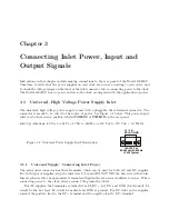
The universal, high voltage power supply comes with a pluggable, three-terminal connector. The
connector is meant to be wired to the source of power. See Figure 3.1 below. This power supply
inlet can be located in a position labeled
POWER A
or
POWER B
on the rear panel.
Inlet Specifications: 85 Vac to 264 Vac, 47 Hz to 440 Hz, or 110 Vdc to 370 Vdc,
<
30 Watts
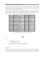
Figure 3.1: Universal Power Supply Inlet Description
L1/
DC+
L2/
DC- GND
100-350 Vdc
85-264 Vac/47-440 Hz
<30 W Typical
3.1.1
Universal Supply: Connecting Inlet Power
The power inlet connector has three terminals, which can be used for both AC and DC supplies.
For both types of supplies, strip the inlet wire 1/4 in and DO NOT TIN the bare wire with solder.
Insert each wire into the appropriate terminal and tighten the set screws clockwise to secure. When
connecting power to the clock, always connect the ground lead first.
For AC supplies, the terminals are indicated as L1/DC+, L2/DC- and GND (for Ground). L1
would be the hot lead, L2 would be neutral and GND is ground. For DC inlet power supplies,
connect the positive lead to the DC+ terminal and the negative lead to DC- terminal.
Summary of Contents for 1201B
Page 4: ...iv ...
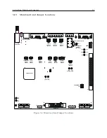
Page 153: ...B 7 Four Fiber Optic Outputs 135 Figure B 4 Jumper Locations ...


