Page 1 of 4
Document #1200608 Rev 3
02/25/2015
HAZARDOUS VOLTAGE:
Risk
of electric shock. Can cause
injury or death. This device may
be connected to more than one
branch circuit. Disconnect all
branch circuits before servicing.
WARNING
STEFFES
CORPORATION
THEBEN
MODEL
“TR610
TOP2”
TIME
CLOCK
REPLACEMENT
AND
SETTING
INSTRUCTIONS
Item #1301007R (120V Clock) and Item #1301008R (240V Clock)
THIS PROCEDURE MUST BE PERFORMED BY A QUALIFIED TECHNICIAN
NOTE: If replacing a non-Theben time clock, an installation kit should be ordered. See Figures 2, 3 and
4. For CCRP’s and Transceivers, order enclosure Item
#1040310.
REPLACEMENT
1. De-energize the system.
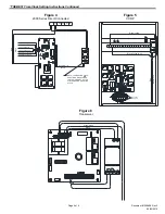
2. For time clocks mounted on din rail, remove the old time clock from the mounting
rail. Pry down on the tab located at the bottom of the clock (Figure 1) and pull
outward.
3. Position the new clock on the appropriate mounting bracket and connect wiring
in accordance with the wiring diagram for the application (see Figures 2 thru 6).
SETTING THE TIME CLOCK
NOTE: The Theben time clock is equipped with a lithium battery with an approximate 4-year power reserve.
Throughout the programming of the time clock, if there is approximately 90 seconds of inactivity (no buttons are pushed),
the display will automatically reset to normal operation. If the clock resets and the program information you are entering
or editing is not stored, the time clock will default to the previous settings. The new information will have to be
reprogrammed.
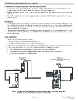
1. The time clock is delivered in a "sleep" mode. To activate without a service voltage, press and release one of the four
buttons.
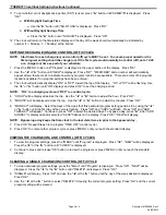
2. Press and hold “MENU” and “OK” buttons until display goes blank. Press “OK”.
NOTE: To navigate through the menus below, press the "
◄
" or "
►
" button. Press the “OK” button to save each
selection and move to the next one..
3. Select the national language.
4. If “Form Date” appears, select the desired format - mm/dd/yy,
yy/mm/dd, dd/mm/yy.
5. Set the current year.
6. Set the current month.
7. Set the current day of the month. This display will show the day
followed by the month (i.e. 09.01 is January 9
th
).
8. If “Form Time” appears – select 12 hr or 24 hr clock.
9. Set the current hour. Ensure the correct am/pm hour is selected
if using a 12 hour clock.
10. Set the current minutes.
NOTE: The time clock should continue with setup of
daylight savings time; however, may return
to normal operating mode and skip daylight
savings section. If this occurs, press
"MENU" button until “
” is flashing at the
top of the display. Press "OK" and repeat
Steps 3-8.
Tab
Figure 1
Contact 1
Contact 2
Contact 3
“ON/OFF”
Indicator
Day of Week
Indicator


