4.2 Verifying Antenna and Cable Operation
17
4.2
Verifying Antenna and Cable Operation
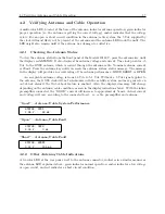
A multi-color LED, located at the base of the antenna, indicates antenna operation; green indicates
proper operation (i.e. the antenna is getting the correct voltage), amber indicates that the voltage
is low. For an open or short circuit condition in the antenna/cable system, the 5 Vdc supplied by
the clock will most likely not be present at the antenna and the antenna LED would be unlit. The
LED might also remain unlit if the antenna was damaged or defective.
4.2.1
Checking the Antenna Status
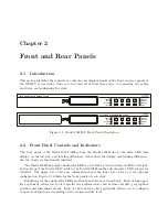
To view the antenna status from the front panel of the Model 1201B/C, press the antenna key until
the display reads
STATUS:
. It also displays the antenna voltage and current. The clock pr5
Vdc to the GNSS antenna, which is carried through the antenna cable. Nominal antenna current
is 29 mA. Press the antenna key until you reach the antenna system status message. The message
in the display will provide an overall rating of the antenna performance:
GOOD
,
SHORT
, or
OPEN
.
An acceptable antenna voltage is from 4.9 Vdc to 5.1 Vdc. Without a 5 Vdc signal applied to
the antenna, the GNSS clock will not synchronize with the satellite system, and may generate an
out-of-lock alarm if the Out-of-Lock feature is enabled. Also, the displayed message will change
depending on the antenna/cable condition, as seen in the display indications below. With the inline
preamplifier connected, the “GOOD” current will increase to approximately 54 mA. Actual current
and voltage will vary according to the connected load – i.e. cable, preamplifier and antenna.
“Good” – Antenna/Cable System Performance
STATUS: GOOD
4.98 V,
29 mA
“Open” – Antenna/Cable Fault
STATUS: OPEN
5.03 V,
0 mA
“Short” – Antenna/Cable Fault
STATUS: SHORT
0.01 V,
125 mA
4.2.2
Other Antenna/Cable Indications
A tri-color LED at the rear panel, next to the antenna connector, indicates in a similar manner as
the antenna LED explained above: green indicates normal operation, amber indicates a low voltage
or open circuit, and red indicates a short circuit condition.
Summary of Contents for 1201B
Page 4: ...iv ...
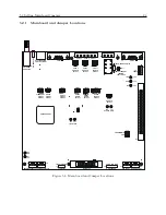
Page 153: ...B 7 Four Fiber Optic Outputs 135 Figure B 4 Jumper Locations ...

