3.4 Connecting Output Signals
13
power from the clock. Use a medium, flat-bladed screwdriver and turn the cover counter-clockwise.
The cover and fuse should pop out.
CAUTION:
Replace fuse only with another of the same type and rating. See Table 3.1 above for
the correct fuse configured for your power supply option.
3.4
Connecting Output Signals
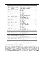
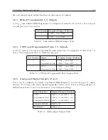
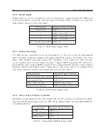
Output signals may be connected through designated standard or option connector. For standard
I/O connectors, see Sections 2.3.7 and Chapter 5. Terminals are Phoenix-type with 5 mm spacing
and will accept between 0.25 mm and 2.5 mm diameter wire. For option boards that have terminals
for output connectors, see the respective section, by option name, in Appendix B for details about
those options and connectors. BNC connectors, on installed option boards, are female and require
only connecting the male connector into it.
To connect wires to any of the terminals, strip the insulation back to expose about 0.25 in of
bare wire and DO NOT tin the bare end with solder. Insert the stripped wire into the terminal
and turn the screw down to secure it in the connector.
3.5
Connecting Input Signals
Input signals may be connected through the designated I/O terminals, the RS-232 connector and
through an installed option connector designated as Input.
For standard I/O connectors, see
Section 2.3.7 and Chapter 5. Terminals are Phoenix-type with 5 mm spacing and will accept
between 0.25 mm and 2.5 mm diameter wire. Optional Four BNC Connectors has four, female
BNC connectors and allows one connection of an input signal for event timing besides the three
output connectors. See Appendix B for details about wiring and connectors for this option. BNC
connectors (on installed option boards) are female and require only connecting the (male) connector
to it.
To connect wires to any of the terminals, strip the insulation back to expose about 0.25 in of
bare wire and DO NOT tin the bare end with solder. Insert the stripped wire into the terminal
and turn the screw CCW to secure it in the connector.
3.6
Fiber Optic Connector
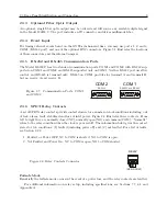
The Model 1201B/C may be equipped with an optional, fiber optic output with ST connector,
located between COM1 serial port and the antenna connector. This output can provide any of
the available digital signals produced in the Model 1201B/C. For additional information on this
optional output, see Appendix B.
3.7
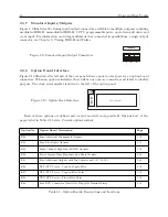
Option Board Space
On the left side of the rear panel is a rectangular space that accommodates a number of different
option boards to increase the functionality of the Model 1201B/C. See Table 2.1 for a list of option
boards, descriptions and locations of information for each option.
Summary of Contents for 1201B
Page 4: ...iv ...
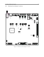
Page 153: ...B 7 Four Fiber Optic Outputs 135 Figure B 4 Jumper Locations ...

