20
GNSS Antenna and Cable Information
DC Resistance
The cross-sectional area and length of the conductors in the cable determine the dc resistance.
Since power to the RF preamplifier in the antenna, and possible inline amplifier, is supplied via the
antenna cable, excessive dc resistance will degrade performance.
Available Antenna Cables and Accessories for Longer Runs
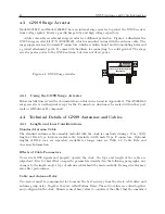
Arbiter Systems offers longer antenna cables for use with all models of clocks when the standard 15
m (50 ft) cable is inadequate. For RG-6 cable runs greater than 250 ft, up to 500 ft, Arbiter offers a
21 dB in-line amplifier, P/N AS0044700. A larger RG-11 style cable is available (P/N WC0004900,
305 m / 1000 ft roll), that can be used for runs to 120 m (400 ft) without the in-line preamplifier,
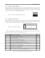
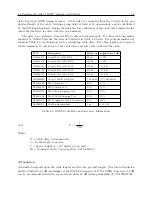
or 240 m (800 ft) with the AS0044700 amplifier. See a list of these accessories in Table 4.2.
Physical Protection
When routing the antenna cable, protect it from physical damage, which may result from closing
doors, falling objects, foot traffic, etc. Also, when routing around corners, allow for sufficient bend
radius to prevent kinks. Extra length should be allowed at both ends of the cable to prevent tension
on the connectors, which could cause damage or failure. Extra length is useful as a service loop, in
the event that a connector needs replacement.
Do not stretch the cable midair over any appreciable distance without support. Cable degra-
dation or failure could result. Always leave a drip loop wherever the cable enters a structure, to
prevent water from entering the structure via the cable jacket. The maximum temperature rating
for the type of cable provided with the clock is 75
◦
C (167
◦
F). Exercise care when routing the
cable near sources of heat to avoid cable damage.
Adjacent Signals
Although the standard RG-6 style cable is triple-shielded and has excellent shielding properties, be
cautious when routing near high power RF sources or alongside cables carrying high power RF, such
as transmitter cables. In these applications, consider using RG-11 style cable (P/N WC0004900).
Its quad-shielded design provides even more isolation.
Antenna Power
The RF preamplifier within the antenna requires 5 Vdc at approximately 30 mA nominal for
operation. A power supply within the clock generates this voltage, which is applied to the antenna
via the two conductors of the coaxial antenna cable.
Avoid shorting the center conductor to
the shield of the coaxial cable as it may damage the preamplifier. Conversely, a high-resistance
connection or open circuit would deprive the preamplifier of power. Either a short circuit or open
circuit condition in the antenna cable will render the clock unable to receive satellite signals.
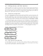
Prior to initial operation or if problems are suspected, go through the tests described in Sec-
tion 4.2.
Summary of Contents for 1201B
Page 4: ...iv ...
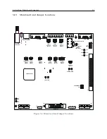
Page 153: ...B 7 Four Fiber Optic Outputs 135 Figure B 4 Jumper Locations ...

