B.7 Four Fiber Optic Outputs
133
B.7
Four Fiber Optic Outputs
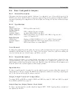
When installed into the standard Model 1201B/C this option provides four individually selectable fiber optic
outputs with Type ST connectors and 820 nm transmitters compatible with multimode fiber.
B.7.1
Specifications
Each fiber optic output is jumper-configurable to each of the standard digital (CMOS) signal outputs available
in the Model 1201B/C. These include unmodulated IRIG-B, 1 Pulse Per Second and Programmable Pulse.
Analog signals, IRIG-B Modulated, and
±
5 V Recorder are not selectable.
Option provides an optical power output of -15 dBm minimum (-12 dBm typical) into 62.5/125
µ
m fiber.
The optical signal is ON whenever the selected logic signal is HI. Transmitter bandwidth is compatible
with all available logic signals.
Cover Removal
To change the configuration of this option, the top cover of the instrument must be removed. Turn off the
instrument, and disconnect the power cord. Using a T25 Torx driver, remove the eight screws holding the
cover (and rack-mount ears, if used) in place, and lift the cover off.
B.7.2
Output Jumper Enable (JMP2 – JMP5)
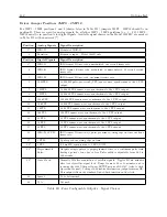
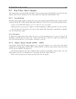
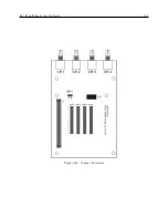
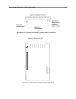
The standard digital (CMOS) output signals can be selected for output via one of the fiber optic output
transmitters by setting jumpers JMP2, JMP3, JMP4 and JMP5 on the fiber optic option board as described
in Table B.2 and illustrated in Figure B.4.
The following tables provide a list of jumpers that correspond to transmitted output signal, and a list
digital signals available for configuration to each specific fiber optic output connector.
JMP1 enables (position A) or disables (position B) all of the outputs.
Summary of Contents for 1201B
Page 4: ...iv ...
Page 153: ...B 7 Four Fiber Optic Outputs 135 Figure B 4 Jumper Locations ...


