background image

A54-3144-XR • Rev B

61

APCON, Inc.

ACI-3144-XR Chassis User Manual

Chapter 5. Configure the chassis

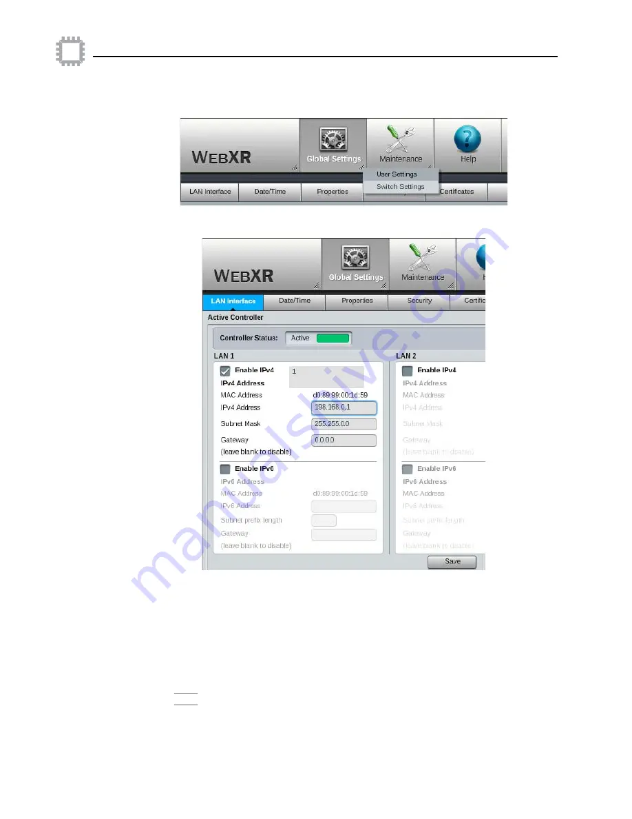
3. This displays the Global Settings toolbar. Click the soft arrow on the Global Settings 

icon and select 

Switch Settings

.

4. On the Switch Settings page, click the 

LAN Interface

 tab.

5. Under the 

Active Controller

 pane, click the checkbox to enable IPv4. (If your network 

uses IPv6 addresses, click the checkbox to enable IPv6 instead.)
a. For LAN 1, click the field for the IPv4 Address and enter a new address.
b. For LAN 1, click the field for the Subnet Mask and enter a new subnet mask.
c. As needed, set a gateway address for LAN 1.

6. (Optional) To enable LAN 2, click the checkbox for

 LAN 2 Enable IP

, and enter an 

IP address, subnet mask, and gateway.

7. Click 

Save

 under the Active Controller pane in W

EB

XR, then close the browser.

Summary of Contents for ACI-3144-XR

Page 1: ...CI 3144 XR Chassis User Manual Four blade chassis Up to 144 ports 4 RU Embedded command line and graphical user interfaces Advanced network monitoring features Packet aggregation with multi stage filt...

Page 2: ...nondisclosure agreement APCON Inc reserves the right to revise this publication from time to time without obligation of APCON to notify any person or organization of such revision APCON has prepared t...

Page 3: ...e ACI 3144 XR chassis 15 Chapter 3 Specifications and compatibility Physical specifications 17 Safety and compliance 18 Power and electrical specifications 18 AC power specifications 19 AC Power Cords...

Page 4: ...nsceivers 35 Connect power to the chassis 35 Connect AC power 35 Connect DC Power 36 Connect the chassis 38 Next steps 38 Chapter 5 Configure the chassis Default settings 39 Use the front panel interf...

Page 5: ...ement of controller battery 68 Blades 69 Transceivers and fiber optic cables 70 Safety precautions 70 Cleaning tools 71 Care of fiber optic cables 71 Install and remove transceivers 73 Clean transceiv...

Page 6: ...APCON Inc 6 A54 3144 XR Rev B Contents ACI 3144 XR Chassis User Manual...

Page 7: ...ed in this manual includes product specifications as well as how to install configure and maintain the ACI 3144 XR chassis Chapter 1 Preface Chapter 1 NOTE In this manual the ACI 3072 XR chassis is us...

Page 8: ...ctices which if not avoided may result in minor or moderate injury or damage to data or hardware ESD Caution Indicates situations that may cause damage to hardware via Electrostatic Discharge ESD Elec...

Page 9: ...MON statistics schedule and implement software upgrades in batch mode and manage user accounts Using TITANXR network traffic running across a KVM hypervisor on a separate Linux server can be mirrored...

Page 10: ...t from APCON contact your sales representative directly APCON Inc standard technical support is available by phone as follows By e mail Sales representative sales apcon com APCON technical support sup...

Page 11: ...en populated with INTELLAFLEX blades these chassis allows you to aggregate filter and direct data to network monitoring and analysis equipment In addition specialty blades offer features such as data...

Page 12: ...ne and SNMP interfaces as well as a front panel that you can use to quickly configure the chassis The ACI 3144 XR chassis work with legacy 1G analysis tools preserving your investment and reducing the...

Page 13: ...eft on all INTELLAFLEX XR chassis and LEDs on the right of each blade displays the state of operational readiness and power All INTELLAFLEX XR chassis are designed for standard 19 inch racks Depending...

Page 14: ...r supplies see Power and electrical specifications on page 18 Embedded software In addition to the hardware specific features APCON embedded software offers the following common software in all INTELL...

Page 15: ...chassis The ACI 3144 XR chassis contains Up to four 4 high density blades in INTELLAFLEX XR chassis Up to 36 ports on each blade a maximum of 360 Gbps throughput per blade with a total of 144 ports av...

Page 16: ...APCON Inc 16 A54 3144 XR Rev B Chapter 2 Introducing the chassis ACI 3144 XR Chassis User Manual...

Page 17: ...y and compliance 18 Power and electrical specifications 18 Specifications for interfaces 23 Compatibility 26 Chassis defaults 29 Chassis Dimensions RU ACI 3144 XR 7 0 x 17 2 x 25 0 inches 17 8 x 43 7...

Page 18: ...ctions AC power AC power specifications on page 19 DC power DC power specifications on page 20 For an INTELLAFLEX XR chassis a power supply can fail without affecting chassis operation Use the WEBXR i...

Page 19: ...XR chassis APCON offers a complete selection of power cords and adapters with different voltages and plug ends to meet electrical requirements in countries around the world as shown in the following...

Page 20: ...cations for the DC power supply in the ACI 3144 XR chassis ACI 0080 525 Type I Australian 3 pin Grounded 220 240 V Australia New Zealand China Argentina ACI 0080 425 Power Extension Cord for rack powe...

Page 21: ...l block for each DC power supply ordered Following are the polarity specifications for the DC power supply The orientation of the slots assumes that you are looking directly at the face of the power s...

Page 22: ...ions other than direct connections to the branch circuit such as the use of power strips An Earth connection is essential before connecting the power supply to the chassis The building installation sh...

Page 23: ...terfaces on an INTELLAFLEX XR chassis LAN ports The LAN ports on the Controller panel manage the network connection from an INTELLAFLEX XR chassis to your network Specifications for the LAN ports 1 an...

Page 24: ...pin outs for the DB 9 adapter are as follows Controller Terminal Signal Connection Pin Signal I O Signal I O 1 CTS Input RTS Output 2 DSR Input DTR Output 3 RXD Input TXD Output 4 GND GND 5 GND GND 6...

Page 25: ...XR chassis Back of the chassis Following are the status indicators on the back of an INTELLAFLEX XR chassis For information about status indicators for the chassis and installed blades displayed in t...

Page 26: ...Aggregator Blade with 5 segments each with 2 network ports and 2 ports to connect to other appliances plus 4 each 1G 10G INTELLAFLEX ports R2 ACI 3030 E32 7 Blade with 32 ports 24 each 1G 10G ports an...

Page 27: ...P N ACI 0240 195 R APCON P N ACI 0240 196 R APCON P N ACI 0240 197 R a bidirectional BiDi transceiver 1 10G SFP Small Form Factor Pluggable transceivers ACI 0201 199 R ACI 0201 200 R Before you insta...

Page 28: ...in the blade use numbers for each port starting at the left A blade may have up to 36 ports per blade For blades with ports in two rows the ports are numbered top to bottom then left to right In softw...

Page 29: ...or an INTELLAFLEX XR chassis Setting Default Value IP address LAN 1 192 168 0 1 default IP address LAN 2 Disabled user configurable Subnet mask LAN 1 255 255 255 0 default Subnet mask LAN 2 Disabled u...

Page 30: ...APCON Inc 30 A54 3144 XR Rev B Chapter 3 Specifications and compatibility ACI 3144 XR Chassis User Manual...

Page 31: ...l fiber optic power and Ethernet cables Acquire any cables you need for the installation Decide which software interface if any you plan to use to set up and control the chassis If you do not plan to...

Page 32: ...nt in a rack should be such that the amount of air flow required for safe operation of the equipment is not compromised The chassis requires that air enters from the left side as you face the front of...

Page 33: ...ns the following items One ACI 3144 XR INTELLAFLEX chassis Four rack mount brackets in the accessory box with screws Four bottom feet for tabletop installations One 7 foot RJ 45 modular 8 wire straigh...

Page 34: ...e appropriate screws Ensure that flanges on both the front and rear of the chassis are secured to the rack If the chassis is installed in a rack with other equipment ensure that you do not overload th...

Page 35: ...nimum Connect AC power Each AC power supply uses a standard power cord that plugs into a standard circuit outlet See AC Power Cords on page 19 for a list of power cords available from APCON To prepare...

Page 36: ...C power supply Any installation of cables to a DC power supply should conform to your organization s established instructions operational requirements or best practices all of which supersede instruct...

Page 37: ...dicators described in the next sections You can also set alarms in the WEBXR interface To verify the operating status of each DC power supply Check the two LED indicators Note the labels beside the LE...

Page 38: ...onfigure the chassis Set the IP address subnet and gateway using the front panel LCD on the chassis or by using WEBXR or CLI Lower LED OUT or OK Normal operation Solid green PSON High Blinking amber O...

Page 39: ...Log into the network connect the unit to the network and use the embedded WEBXR software Log into the network connect the unit to the network and use the embedded command line interface CLI Each of t...

Page 40: ...rom within WEBXR interface under the System icon see the WEBXR User Manual for details Control buttons The touch screen control buttons at the bottom of the LCD screen provide the following functions...

Page 41: ...TER button The Main Menu is displayed on the LCD screen The Main Menu lists the following sub menus Sub menu Description Status see page 42 Displays the alarm status login count and users currently lo...

Page 42: ...tus menu option is selected then press ENTER The following screen is displayed The status information displayed varies by the number of and type of blades and power supplies installed in the chassis I...

Page 43: ...setting Absent The fan cage has been pulled out of the chassis Shutdown The fans have been powered OFF long enough that the chassis has shut down the backplane to protect the chassis from overheating...

Page 44: ...ve Identifies the physical location of the Active Controller installed in the chassis Primary Slot The Active Controller is in the lower Primary slot default Secondary Slot The Active Controller is in...

Page 45: ...e switch Successful The number of log in attempts that succeeded Failed The number of log in attempts that failed Online Users Lists identifying information for users currently logged into the switch...

Page 46: ...ccess the IPv4 Menu press DOWN to scroll through the sub menus on the Config Menu until the IPv4 Config menu option is selected then press ENTER The following screen is displayed Option Description En...

Page 47: ...o an available static IPv4 address on the network The controller supports two LAN ports You must set an IPv4 address for the LAN1 port to be able to access the switch over a network Setting an IPv4 ad...

Page 48: ...rsor to the left press CANCEL 3 When the cursor is positioned over a digit you want to change press either UP or DOWN to increase or decrease the value 4 When the desired digit is displayed press ENTE...

Page 49: ...digit is displayed press ENTER to confirm the setting and move the cursor to the right over the next digit 5 Repeat the steps above until the desired netmask is displayed 6 When the desired netmask i...

Page 50: ...ay to the right and the IPv4 Menu is redisplayed 7 To save the gateway address press DOWN repeatedly until the Save Changes option is marked on IPv4 Menu and then press ENTER Configuration IPv6 Config...

Page 51: ...ng screen is displayed 2 To set the desired IP address use the CANCEL and ENTER buttons to position the cursor over the first digit you want to change To move the cursor to the right press ENTER To mo...

Page 52: ...nd ENTER buttons to position the cursor over the first digit you want to change To move the cursor to the right press ENTER To move the cursor to the left press CANCEL 3 When the cursor is positioned...

Page 53: ...is positioned over a digit you want to change press either UP or DOWN to increase or decrease the value 4 When the desired digit is displayed press ENTER to confirm the setting and move the cursor to...

Page 54: ...og ins allowed Configuration Restart Services To access the Restart Services menu press DOWN to scroll through the sub menus on the Config Menu until the Restart Services menu is selected then press E...

Page 55: ...gh security environments may find the Wipe function useful before passing the APCON chassis or the Controller to another department or to the factory for example to track an RMA return trade or upgrad...

Page 56: ...nus on the Main Menu until the Failover menu is selected then press ENTER The following screen is displayed The Failover Menu lists the following sub menu option Option Description Wipe Deletes all co...

Page 57: ...is displayed The Failover NOW option allows you to swap controllers in event that the Active Controller begins to fail This assumes there are two controllers installed in the switch When you select t...

Page 58: ...igured for the chassis If the IP address is not configured the display is n a Netmask n Subnet mask configured for the chassis The default is 255 255 255 0 If Netmask2 is not configured the display is...

Page 59: ...wser that supports Adobe Flash Player v18 0 or greater see page 9 for web browsers supported An IP address subnet mask and gateway if required appropriate for your network to assign to the chassis Che...

Page 60: ...ured to use a proxy server disable the proxy setting c In the browser s address field URL enter http 192 168 0 1 7 Log into WEBXR using the default administrator name and password User name admin Pass...

Page 61: ...pane click the checkbox to enable IPv4 If your network uses IPv6 addresses click the checkbox to enable IPv6 instead a For LAN 1 click the field for the IPv4 Address and enter a new address b For LAN...

Page 62: ...type http X X X X replacing the X s with the IP address you specified for the chassis The WEBXR log in screen is displayed 3 Enter the default user name and password User name admin Password secret Th...

Page 63: ...4 On the Switch Settings page click the Properties tab 5 Select the Chassis tab 6 Enter a new name for the chassis in the field for Chassis Name in the dialog box The chassis name may contain up to 31...

Page 64: ...rogram to connect then use the CLI commands to configure the chassis Before you begin using CLI To configure the IP address subnet mask and gateway using CLI you need the following An IP address subne...

Page 65: ...The console prompt from the chassis is displayed in the communication program s window 4 Set the IP address by entering the following command configure ip For example Parameter Value Port COM1 Bits pe...

Page 66: ...console prompt enter the following CLI command Step 4 Access the chassis using CLI 1 On a computer with network access to the chassis open a Telnet or SSH client 2 Telnet to X X X X replacing the X s...

Page 67: ...install controllers Remove and install the Fan Module Perform a system recovery Chapter 6 Maintain the chassis Chapter 6 Blades 69 Transceivers and fiber optic cables 70 Power supplies 74 Controllers...

Page 68: ...er battery The Controller in the chassis is equipped with a battery However the battery on all APCON controllers is not accessible and is therefore not a serviceable part The battery cannot be replace...

Page 69: ...er off the blade before removing it You do not have to power off the entire chassis a In WEBXR click the soft arrow in the lower right corner of the blade b From the pop up menu that is displayed sele...

Page 70: ...As you work with the chassis you may need to install remove reposition clean or replace transceiver modules or fiber optic cables It s very important to keep transceivers and cables clean and covered...

Page 71: ...ts If you have a cleaning kit follow the instructions included with the kit Care of fiber optic cables Careful handling of fiber optic cables extends the life of optical transceivers Here are some pre...

Page 72: ...d air 2 Drip one to three drops of methanol or isopropyl alcohol onto a sheet of lens paper or a lint free cloth 3 Holding the connector well below the optical surface place the wet portion of the len...

Page 73: ...t click 4 Depending on the number of ports and the orientation of ports on a blade you may need to flip a transceiver over so the label faces the other direction For example an ACI 3030 E36 6 blade ha...

Page 74: ...odule 1 Grasp the module firmly 2 Blow clean compressed air into the inner barrel of the module 3 Examine the surface of the optical sub assembly under high intensity light using a microscope or verif...

Page 75: ...The number of fans on the tray for that Fan Module may vary depending on the chassis however the entire Fan Module in any INTELLAFLEX XR chassis is swapped at one time The time involved to swap out t...

Page 76: ...pted When installing a new controller you must first set up the IP address then either import switch settings and user data or again set up aggregations If there are two controllers installed in the c...

Page 77: ...ce see how to Contact APCON on page 10 Be prepared to provide details about hardware installed in the system as well as the current version of software This section describes a recovery process when a...

Page 78: ...y upper slot Software The state of a controller is displayed on the Status screen in WEBXR as either the Active Controller or Standby Controller if any The controllers can be located in either physica...

Page 79: ...ys the Global Settings toolbar Click the soft arrow on the Global Settings icon and select Switch Settings 4 Click the tab for the LAN Interface 5 On the right side of the screen check the Controller...

Page 80: ...ables into all power supplies in the chassis to turn power ON 3 Observe the LEDs on the Primary Controller in the lower slot in the chassis After the green LED displays as a solid state power on it be...

Page 81: ...ashing and the LED displays as a steady or solid green light on the Primary Controller release the interior Reset Switch and remove the paper clip This reboots the Primary Controller and resets it to...

Page 82: ...these steps To complete the recovery process 1 Log into WEBXR Because all settings have been wiped from the controller you must log in using the default settings User name admin Password secret It is...

Page 83: ...nload the current version of software from the APCON Support Site https support apcon com also download and read the following documents Software Release Notes for the version of software you want to...

Page 84: ...APCON Inc 84 A54 3144 XR Rev B Chapter 6 Maintain the chassis ACI 3144 XR Chassis User Manual...

Page 85: ...ived 25 supported 26 27 browser 9 Firefox 9 Google Chrome 9 Internet Explorer 9 supported 9 version supported 9 C cable fiber optic 71 handling 71 switch to host computer 59 switch to network 62 Cauti...

Page 86: ...n Menu 45 control buttons 40 home screen 41 G Gateway address 61 example 49 53 LAN 1 default 29 LAN 2 default 29 LCD menu 47 LCD switch information screen 58 set using WEBXR 59 Google Chrome 9 GRE tun...

Page 87: ...tic cables 72 clean transceivers 74 remove and replace controller 76 remove and replace fans 75 remove and replace power supplies 74 upgrade system software 82 maximum cable length 23 Microsoft Intern...

Page 88: ...ion 58 Mobile App 9 upgrade with WEBXR 82 software products 9 specifications AC power 19 DC power 20 interfaces 23 physical 17 power and electrical 18 safety and compliance 18 switch defaults 29 SSH 9...

Page 89: ...mit signal TX 25 troubleshooting transceivers 27 TX signal 25 U UL 18 unpack the carton 33 user manual contents 7 user selectable rates 27 V ventilation slots 34 W web browser Chrome 9 Firefox 9 Inter...

Page 90: ...APCON Inc 90 A54 3144 XR Rev B Index ACI 3144 XR Chassis User Manual...

Reviews: