UG-707
ADV8005 Hardware Reference Manual
Stop and start conditions can be detected at any stage during the data transfer. If these conditions are asserted out of sequence with normal read
and write operations, these cause an immediate jump to the idle condition. During a given SCLK high period, the user should issue only one
start condition, one stop condition, or a single stop condition followed by a single start condition. If an invalid subaddress is issued by the user,
the
does not issue an acknowledge and returns to the idle condition.
If the user exceeds the highest subaddress in auto increment mode, the following actions are taken:
•
In read mode, the highest subaddress register contents continue to be output until the master device issues a no acknowledge. This
indicates the end of a read. A no acknowledge condition is where the SDA line is not pulled low on the ninth pulse.
•
In write mode, the data for the invalid byte is not loaded into any subaddress register. A no acknowledge is issued by the
and the part returns to the idle condition.
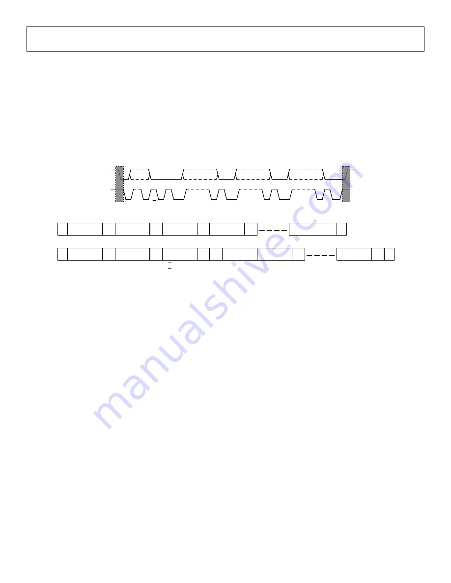
Figure 8: Bus Data Transfer
Figure 9: Read and Write Sequence
1.4.
The
requires a number of configuration settings for each mode of operation. To ensure the part is correctly configured, refer to either
the recommended settings configuration script (supplied with the
evaluation software) or the reference software driver. Failure to
follow these recommended settings will result in the part not operating to its optimum performance.
S
1-7
8
9
9
9
P
Device
Address
1-8
9
Register
Address (MSBs)
Register
Address (LSBs)
Data
ACK
R/W
1-8
1-8
ACK
ACK
ACK
SDA
SCL
S
1-7
8
9
9
9
P
Device
Address
1-8
9
Register
Address (MSBs)
Register
Address (LSBs)
Data
ACK
R/W
1-8
1-8
ACK
ACK
ACK
S
1-7
8
9
9
9
P
Device
Address
1-8
9
Register
Address (MSBs)
Register
Address (LSBs)
Data
ACK
R/W
R/W
1-8
1-8
ACK
ACK
ACK
SDA
SCL
S
Device
Address
A/(S)
Register
Address [MSBs]
Register
Address [LSBs]
A/(S)
Data
A/(S)
A/(S)
Data
A/(S)
S
Device
Address
A/(S)
Register
Address [MSBs]
Register
Address [LSBs]
A/(S)
Data
A/(S)
A/(M)
Data
A/(M)
S
Device
Address
P
P
S = Start Bit
P = Stop Bit
A(S) = Acknowledge by Slave
A(M) = Acknowledge by Master
A(S) = Acknowledge by Slave
A(M) = Acknowledge by Master
S
Device
Address
A/(S)
Register
Address [MSBs]
Register
Address [LSBs]
A/(S)
Data
A/(S)
A/(S)
Data
A/(S)
S
Device
Address
A/(S)
Register
Address [MSBs]
Register
Address [LSBs]
A/(S)
Data
A/(S)
A/(M)
Data
A/(M)
S
Device
Address
P
P
S
Device
Address
A/(S)
Register
Address [MSBs]
Register
Address [LSBs]
A/(S)
Data
A/(S)
A/(S)
Data
A/(S)
S
Device
Address
A/(S)
Register
Address [MSBs]
Register
Address [LSBs]
A/(S)
Data
A/(S)
A/(M)
Data
A/(M)
S
Device
Address
P
P
S = Start Bit
P = Stop Bit
A(S) = Acknowledge by Slave
A(M) = Acknowledge by Master
A(S) = Acknowledge by Slave
A(M) = Acknowledge by Master
Rev. A | Page 24 of 317


