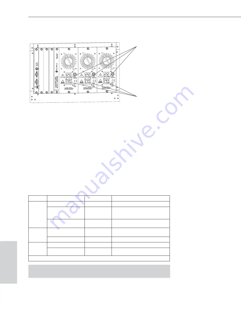
5. Toggle the power switches (see Figure 14) on the power supplies on.
6. Turn on the power strip (to all enclosures if applicable).
7. Apply power to the control device/system.
8. Check the indicator lights (see below).
9. Apply power to any controllers, SDUs, or other peripheral devices.
10. Apply power to the source and destination devices.
The system is ready for a test switch (see Chapter 7).
For startup information on specific types of control, see page 6-3 before
executing a test switch.
Indicator LEDs
When the enclosure powers up successfully, the indicator lights will respond as
follows:
Indicator
Normal Display
Cautionary Display
Front
Panel
POWER (power status)
Green
RPS (redundant
power supply)
Green
If red - check the power supplies
power status LEDs at rear of the
enclosure
COMM (controller
communication status)
Blinking green
Power
Supply
STATUS
Green
If blinking green - the power supply is
not bound to the enclosure*
POWER
Green
Blinking red indicates failure
CPU
COMM
Blinking green
STATUS
Blinking green
LED may initially flash green or red,
before blinking green
* The procedure to bind a power supply to the enclosure is in the X
N
Connect Help file.
Important:
If the indicator lights do not respond with a normal display as
stated above, contact technical support (see page 7-3).
6-2
Epica-128 & Epica-256 Installation & Setup
Applying Power & Startup
Power
&
Startup
Figure 14: Power supplies on an Epica-128
Power switches
Fuse trays


