(if COM port settings do not match, enter the applicable values from the
Epica table). Click OK. A short splash screen appears.
4. Perform a test switch to ensure the Epica is working properly (see Chapter 7,
“Executing a Test Switch”).
4.2 Attaching External X
N
Net Controllers
An X
N
Net device is any device that sends and receives X
N
Net protocol over the
Link (X
N
Net) port. AutoPatch X
N
Net control devices include remote control
panels, such as the CP-20A or CP-10. AutoPatch X
N
Net accessory devices
include SBCs, Preset SBCs, SDUs (Status Display Units), etc.
The instructions below are for attaching a device to the Link (X
N
Net ) port,
found on the CPU board. For more information, see the individual device’s
documentation.
Communication Cable
Requirements
q
A two-conductor, 20 AWG, 7/28 strand cable with a drain wire or shield,
such as Alpha 2412C (customer supplied)
q
Maximum length of cable: 1,000 ft. (304.m) total, including linked panels
To establish a Link port connection with an X
N
Net device:
1. Attach one end of the X
N
Net link cable to the corresponding port on the
device (see the individual product documentation).
2. On the CPU, unplug the Link connector.
3. Loosen the screws on the Link connector.
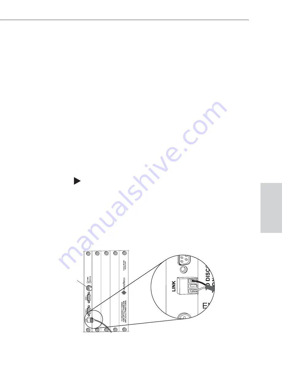
4. Insert the two wires of the X
N
Net link cable from the device into the Link
connector leaving the center slot empty (see Figure 13).
Note that either wire can be inserted into either of the outer slots.
Epica-128 & Epica-256 Installation & Setup
4-5
Attaching & Setting Up External Serial Controllers
Ext
e
rnal
Cont
rol
ENC 2
Figure 13: Insert wires into X
N
Net connector on CPU
50 ohm
termination connector


