AMF REECE S100 Parts And Service Manual Download Page 31

1-26

S100

Revised 10/2005

e-mail: [email protected] ; [email protected]; website: www.amfreece.com

Phones: +420 582 309 146 (Service), +420 582 309 286 (Spare Parts); Fax: +420 582 360 606


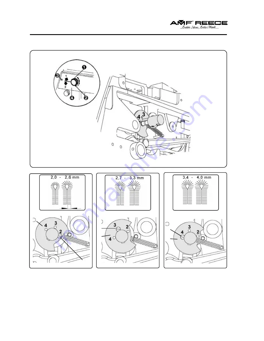
       D -MACHINE ADJUSTMENT

4

3

Ï

Ï

Ï

Î

Î

Î

2

Summary of Contents for REECE S100

Page 1: ...EL S 100 EYELET BUTTONHOLE MACHINE PARTS AND SERVICE MANUAL MACHINE SERIAL No PART NUMBER 97 1700 1 004 AMF is trademark of AMF Group Inc 02 2 0 0 6 This manual is valid fromthe machine serial No J173...

Page 2: ...eNumber Supervising Mechanic s or Technician s Name Signature of Supervising Technician AMF Reece Technician s Name AMF Reece Technician s Signature Type of garment produced at this location Average D...

Page 3: ...ervice labor warranty for machines sold as uninstalled Equipment installed without the assistance of a certified technician either an AMF Reece Employee a Certified Contractor or that of anAuthorized...

Page 4: ...on 1 14 C OPERATOR INSTRUCTIONS 1 Preparing to Sew 1 15 2 NeedleInstallation 1 16 3 Threading 1 16 D MACHINEADJUSTMENTS 1 Stitchesdensityadjustment 1 19 2 Adjustment of the stitches density in the eye...

Page 5: ...pace Change 1 59 5 Clampfeetusingforcorrectbuttonholesewing 1 59 6 Adjustment of the supplied accessories 1 60 F MACHINEADJUSTMENT CROSS BAR 1 Introduction 1 61 2 Differentpositionofthemachinemechanis...

Page 6: ...wo threads machine with chain stitch and opportunity insert the gimp for sewingbuttonholeswithcrossbarand flybar Itallowssewingbyonechainthreadstitch whichissuitable forsmallerhighlightingof thestitch...

Page 7: ...NPE 50Hz 230V TN S 3NPE 50Hz 400V TN S 8 16 stitches cm 64 kg 143 lb 64 kg 143 lb 780 mm 31 height x 1100 mm 43 length x 600 mm 23 6 width 149 kg 149 kg standard cutting after CA possible setting cutt...

Page 8: ...ot cover all safety aspects that is why operator before using of the machine has to read and understand to this instruc tions Themistakeswillbeeliminatedduringmachineinstallationandduringitsownoperati...

Page 9: ...ine to the power if some cover is removed WA R N I N G Remember the position of the operating switch circuit breaker so that is possible use it from the arbitraryposition Makesure whethersupplyofenerg...

Page 10: ...Thatiswhyeverybody whowillmanipulate maintainoroperate withthismachinemustbe acquaintedwithinformationsincludedinthismanual C A U T I O N Performallregularserviceasdescribedbythismanual If there is a...

Page 11: ...er of the drive rear folding cover motor cover Label of the safety conductor clip Necessity of the safety goggles using sewing head front part above the needle Externalcoversofthemachinefoldingordisma...

Page 12: ...re accidentally put into this place it can occur very serious injury Front cover of the frame and lock screw of the folding rear cover which disable tilting of the rear cover are dismantled during tra...

Page 13: ...If the delivery was damaged during the transport inform the carrier Check the contains of thedeliverywithorder Incasethattherearesomefaults immediatelyinform themanufacturer latercomplainswillnotbeta...

Page 14: ...be kept according to the section DOCUMENTATION Wiring diagrams CAUTION The wiring assembly can perform only the person who has an appropriate electrical qualification 2 Afterputtingthetabletogetherand...

Page 15: ...leyforsewingdrivemax875rev min Higherrevolutioncan cause serious machine damage The socket for plug of power supply has to comply with requirements of norm IEC 364 4 41 4 Insert tall rubber washers fr...

Page 16: ...eningthescrewoftherightcoverand itsremoval 10 If the left drive belt is not put on the upper pulley of the head tilting the rear cover to have the access to this belt after loosening the inner screw o...

Page 17: ...ENSION FOR SEWING Thedrivingbeltisplacedundertherightsidecover Afteritsdismantling loosenthepulleyscrewandadjust the V belt pulley so that so that during pushing on the front branch of the belt there...

Page 18: ...e obtained after folding of the folding rear cover 2 Thenadjusttheidlerpulleyuntil13mm 1 2 offlexisobtainedinthebelt asillustrated 3 Tightentheidlerpulleylockingscrews 4 Install the motor covers and s...

Page 19: ...EAD STAND INSTALLATION 1 Put the thread stand together accordingtothedrawing 2 Positionofthelockingring allows assembly of the thread stand forvariousthicknessofthetable top Threaded end of the post m...

Page 20: ...ng correctly it is recommended to sew a few buttonholes on a scrappieceofmaterialbeforesewingonaqualitygarment 8 Insertthematerialundertheclampfeet 9 To lower the clamp feet move the lever forward 10...

Page 21: ...stall a bent or broken needle Roll the needle on a flat surface to check for straightens The good quality needle does not have a deflection of the point 3 Tightentheneedlelockingscrew well 3 THREADING...

Page 22: ...146 Service 420 582 309 286 Spare Parts Fax 420 582 360 606 Threading the gimp and upper thread to the machine S 100 030 031 032 033 035 036 052 053 C OPERATOR INSTRUCTIONS Upperthread Gimpthread To...

Page 23: ...e amfreece cz parts amfreece cz website www amfreece com Phones 420 582 309 146 Service 420 582 309 286 Spare Parts Fax 420 582 360 606 C OPERATOR INSTRUCTIONS Lower thread Lowerthread Use the manual...

Page 24: ...ction 1 to increase the stitch density in direction 2 to decrease stitch density 4 Tightenthenut Note The limiter is installed on the lever To obtain the stitch density 8 9 stitches cm shift the rod s...

Page 25: ...der normal use the brake band will need to be adjusted again The reason is to run in the brake band 1 Loosen the locking nuts 2 By rotating the nuts is moving the brake band in direction 4 to increase...

Page 26: ...nd right hand sides 1 Loosen the locking nut of the adjustment screw in the main shaft brake 2 Adjust the brake pressure to obtain equal stitch density between the stitches Tighten the adjusting screw...

Page 27: ...nd S 100 053 1 Fold the rear cover 2 Loosen the screws and Move with shim forward operator and the stitch density will de crease 3 Tighten the screws and 3 ADJUSTMENT OF THE STITCHES DENSITY IN CROSS...

Page 28: ...p screw and move with the rod till so that the needed sewing length on the dial rod is covered with the indicator mark 2 Tighten the screw The total length of the sewing L was just adjusted see pictur...

Page 29: ...ift the roll stud so that the locking lever allows the insertion of new lateral cam 3 Tightenthescrew No bar to adjust the fly bar with open end of the buttonhole follow this steps 1 Loosen the screw...

Page 30: ...1 3 1 0 5 3 1 4 7 6 0 0 7 1 5 3 1 5 1 4 7 6 0 0 7 1 2 1 0 4 3 1 4 7 6 0 0 7 1 5 3 0 5 1 4 7 6 0 0 7 1 0 1 0 3 3 1 4 7 6 0 0 7 1 2 3 3 1 0 5 0 4 4 7 6 0 0 7 1 5 3 4 0 4 4 7 6 0 0 7 1 D MACHNE ADJUSTME...

Page 31: ...26 S100 Revised 10 2005 e mail service amfreece cz parts amfreece cz website www amfreece com Phones 420 582 309 146 Service 420 582 309 286 Spare Parts Fax 420 582 360 606 D MACHINE ADJUSTMENT 4 3 2...

Page 32: ...to the top of the pivot After the buttonhole is sewn is the bracket in the front of the pivot During the sewing the cross bar the bite size is decreased If the bracket fall down to the front of the p...

Page 33: ...ite www amfreece com Phones 420 582 309 146 Service 420 582 309 286 Spare Parts Fax 420 582 360 606 D MACHINE ADJUSTMENT 7 PRINCIPLES OF SEWING S 100 machine produced byAMF Reece sews two thread chain...

Page 34: ...spreader R H looper Gimp Throatplate D MACHINE ADJUSTMENT Astitchistheunitofthreadformedintheproductionofseamsandstitching Stitchingisdefinedasaseriesofstitchesembodiedinamaterialforornamentalpurpose...

Page 35: ...e lower thread the left hand looper and the spreader fullyenterthe formedloop L H looper Needle L H spreader Lowerthread Upperthread R H spreader R H looper Gimp Throatplate L H looper Needle L H spre...

Page 36: ...er thread up into the material andbringsthelowerthreadwithit Needleguard Needle Throatplate Lowerthread Upperthread R H looper spreader Gimp Needleguard Needle Throatplate Lowerthread Upperthread R H...

Page 37: ...eloopercarriercontinuesmovingtotheleft Theright handlooperandspreaderfullyentertheformed loop The right hand spreader opens making room for the needle to pass through a loop formed by the upper thread...

Page 38: ...ormed thread loop are pulled up against the mate rial The enveloped cord provides the buttonholes with body D MACHINE ADJUSTMENT The looper carrier moves to the right as the needle strips the loop pre...

Page 39: ...ter moving to the sameplaceafterraceturning 3 Possible difference adjust after loosing the nut stud of the cam by its shifting to reach identical distance x1 x2 Tightenthenutwell 9 SETTING OF THE CAM...

Page 40: ...en the screw 3 Loosen the screw and adjust the needle bar so that tension discs are in direction towards the operator Tighten the screw If the stitches are not in direction to the centre of the eye fo...

Page 41: ...ween gauge and the left table slat again The position is correct if there is no clearance between the gauge and the straight edge the edge is parallel to the table slat Ifnot modifytheturningofthesewi...

Page 42: ...to prevent accidental engagement of the machine Rotatethehandleuntilthemachineisinthehomeposition Inthehomeposition thebedplatenolonger moves to the rear This adjustment is pursued when cutting after...

Page 43: ...0 05 0 1 mm Spool Leftdrive pulley 2 3mm Dogs Screw Byturningthehandwheelandwhentherollerisinthehighestpositionofthelengthgauge adjust the clearance 0 1 0 2 mm 0 004 0 008 between the stud and disenga...

Page 44: ...er stud Holderofthearmfoot Screw of the holder The standard clearance between the clamp feet and the needle surface is 1 mm To change the standard bite size 2 8 3 4 mm 0 110 0 134 to bite 2 0 2 8 0 07...

Page 45: ...ciallythin should causestitchesmissing Rotate the left handle until the clamp plate rollers are positioned to the widest part of the spreader block After loosing the locking screw of the clamp change...

Page 46: ...Place a piece of paper across the clamp area of the bedplate to check needlepenetration 4 Switch on the motor power 5 Sew the sample and check regularity of the eye shape sewing Remove appropriate fa...

Page 47: ...ght gauge and check the needle bar height with the needle bar set at the bottom of the stroke Standard height of the needle bar is 16 5 mm 0 65 between the top of the gauge cutout and the bottom of th...

Page 48: ...loopers and needle is 0 05 to 0 1 mm 0 002 to 0 004 1 Manually rotate the right hand wheel and ensure the distance between the needle and each looper as the needle passes the loopers at the closest po...

Page 49: ...e hole in the left looper Inner side of right spreader adjust to the same level with appropriate inner side of the right looper It is possible to do adjustment after loosing the screws of the stop by...

Page 50: ...nter puncture Lift the machine head and after loosing of the screws of the clutch is possible to turn by the sewing cam untilthetiminggaugelinesarealigned whichdeterminesthecorrectpositionoftheloopers...

Page 51: ...the needle Needle bar must lean on the highest point of gauge Now it is necessary to loosen the screws and move the left hand looper to the right or left to bring the looper into the needle center lin...

Page 52: ...ote the position of the right looper point to the center line of the needle If the looper point is not to the center line of the needle loosen the clip screw and move the right hand looper half the di...

Page 53: ...o that the left and right spreader is opening and closing equally on theleftandright withoutcontactingtheneedle Carefully loosen the spreader crosshead set screw located in the spreader spindle It is...

Page 54: ...right as needed 2 Tighten the studs Note If the buttonhole cut looks like illustration1 rotate the studs to the right if the buttonhole cut looks like illustration 2 rotate the studs to the left 3 Aft...

Page 55: ...of the cutting lever and the knife holder are not damaged 3 Installthenewcuttingsteel intotheknifeholderandinstallthenewknifeintothecuttingleverand lightlytightentheknifelockingscrews 4 Manuallylower...

Page 56: ...osition a piece of fabric between the knife and the cutting steel and cycle the machine and check the cut of the fabric The cut must be even and can not be discontented through the whole length If is...

Page 57: ...s rows position increase or decrease the cutting space it is used especially when the cuttingbeforeischangingtothecuttingafter 1 Loosen the nut 2 Turn the eccentric clockwise for the more cutting spac...

Page 58: ...ng nut above and screw of the feet control lever down and by shifting in grooves in direction to the marked stops as needed CA is cutting after and CB is cutting before The stop screws are ensured by...

Page 59: ...angleofsetcuttingknife adjust by scerw so taht the left side ofthe knifeiscoveredwithrightsideofthe throad plate 3 Theknifeposition requiredforcatching the upper thread loop can be changed after loose...

Page 60: ...he point of the right hand looper measured during the moment the actuator passes over the pawl so that is between lever and throated trimming knife arm clearance 0 0 mm to 0 1 mm 0 0 to 0 004 see pict...

Page 61: ...e the lift the lever to the upper position is necessary to loosen the clamping screw and turn the sprung stud for increase of the pressure of the returnablespring 4 For attainment the same length of t...

Page 62: ...TION OF THE MACHINE MECHANISMS S 100 052 053 Onlysomeofthemachinemechanismshavedifferentfunction thanbasictypeofthemachine Tothese mechanismsbelongmechanismforchangeofdiameterofroundbuttonhole whichre...

Page 63: ...he brake shoe and the right hand stop wheel clearance to 0 25 mm 0 010 Using the control screw adjust the gap bolt to 0 4 mm 0 016 0 25 mm 010 0 1 to 0 2 mm 004 to 008 2 1 To adjust the sew start mech...

Page 64: ...tperformedthechangeofstandardlysuppliedroundfootconfiguration 5 CLAMP FEET USING FOR CORRECT BUTTONHOLE SEWING The machine is equipped by the special round feet The figure ex plainsprincipleandconstru...

Page 65: ...tment will be done according to the section MACHINE ADJUSTMENT Loopers adjustment The upper disk ensures enough thread is supplied to correctly start the next eyelet buttonhole Fit it instead ofstanda...

Page 66: ...ed all possible collisions of parts occasioned by the machine operator To guarantee correctmachinefunctions itisnecessarytofollow nextchaptersofadjustment 2 DIFFERENT POSITION OF THE MACHINE MECHANISM...

Page 67: ...ing the screw adjust the lever to obtain the clearance 1 5 mm between the lever and the cam 3 Using the hand crank move the table to the rearward position from the operator The lever in this position...

Page 68: ...tch By moving it backwards from the operator to decrease the length of the second row of stitches picture 1 b By moving it forward in direction to the operator to decrease the length of the first row...

Page 69: ...e cross bar sewing to the cam from the accessories as needed with eye withouteye andwith neededlength 3 Replace the cam according to chapter D 5 4 Use the eccentric stud to move the lever to the posit...

Page 70: ...feeding hand crank Loosen the screw and the screw unscrew at all If the table is in basic position loosen the screw of the lock which replace upwards Remove the right side cover and press the locking...

Page 71: ...icture 1 move it right Correct adjustment is shown on the picture 3 4 Tighten the screws and Thelever mustlightlyfallsonthestud E v e n f e e d i n g i n t h e c r oss ba r To adjust the feeding use t...

Page 72: ...otations min If the machine S 100 060 sewing cross bar will be readjusted to fly bar sewing machine for long time it is also possible to change the sewing speed 1 Change the belt on the pattern of dri...

Page 73: ...nyfaultinelectricalpowersupply switchofftheoperatingswitch circuit breaker Do not damage correct and remove safety labels Do not work with the machine when you are under the influence of drugs or alco...

Page 74: ...ent place the new one and assemble the device in reverse order 5 Performvisualcheckofmechanismespeciallyin areaofsewingmechanism 6 When the maintenance and checking is finished close covers put back t...

Page 75: ...seoilESSOTERESSO 80 90 2 The amount of oil on the reservoir is indicated by the red mark Toomuchoilmaycauseitsoverflowingintheneedle bar area and smear the fabric 3 Thereservoirisfilledapproximately10...

Page 76: ...1 2 Auxiliary oil reservior 2 2 2 2 3 3 1 4 MACHINE DISPOSAL 1 Toensuremachineecologicaldisposalitisnecessarytoremoveespeciallynonmetallicpartsfromthe machine To take these parts out it is necessary...

Page 77: ...1725 rotation a minute 50 60 Hz 550W After machine connection is necessary to ensure electrical power supply of the machine in every fuse by the thermal fuse 10 A Electricalwiringofthetableissuppliedf...

Page 78: ...Revised 10 2005 e mail service amfreece cz parts amfreece cz website www amfreece com Phones 420 582 309 146 Service 420 582 309 286 Spare Parts Fax 420 582 360 606 H DOCUMENTATION A S S E M B LY D I...

Page 79: ...e mail service amfreece cz parts amfreece cz website www amfreece com Phones 420 582 309 146 Service 420 582 309 286 Spare Parts Fax 420 582 360 606 H DOCUMENTATION D I A G R A M O F C O N N E C T I O...

Page 80: ...e mail service amfreece cz parts amfreece cz website www amfreece com Phones 420 582 309 146 Service 420 582 309 286 Spare Parts Fax 420 582 360 606 H DOCUMENTATION D I A G R A M O F C O N N E C T I O...

Page 81: ...e mail service amfreece cz parts amfreece cz website www amfreece com Phones 420 582 309 146 Service 420 582 309 286 Spare Parts Fax 420 582 360 606 H DOCUMENTATION D I A G R A M O F C O N N E C T I O...

Page 82: ...e mail service amfreece cz parts amfreece cz website www amfreece com Phones 420 582 309 146 Service 420 582 309 286 Spare Parts Fax 420 582 360 606 H DOCUMENTATION D I A G R A M O F C O N N E C T I O...

Page 83: ...1 78 S100 Revised 10 2005 e mail service amfreece cz parts amfreece cz website www amfreece com Phones 420 582 309 146 Service 420 582 309 286 Spare Parts Fax 420 582 360 606...

Page 84: ...Machine fails to clamp material or releases the material too soon 2 3 Machinefailstoreleasethefabricclamp 2 3 Unevenclampfeetpressure 2 4 Machinefailstocutthefabric 2 4 Cuttingleverfailstoreturn 2 4...

Page 85: ...the drive belt Left side of the drive belt is too loose 1 37 Correctly position the collar and tighten the screw Electrical equipment defect Change the drive lever spring or correct the idler pulley t...

Page 86: ...d drive member Incorrect treadle mechanism setting Correctly adjust the mechanism Incorrect disengagement lever setting Damaged or weak strating lever spring Replace the spring 17 0026 0 214 or increa...

Page 87: ...the spring 17 0026 3 013 Incorrect R H looper timing Adjust the needle to the looper timing Bent or scratched looper Replace the looper Damaged knife Tighten the screws Loose machine frame csrews Dama...

Page 88: ...e Damaged or incorrectly installed needle Replace the needle Correct the looper and the needle timing Incorrect looper and needle timing Correctly equal the distance on the left and right hand sideof...

Page 89: ...t and cam brake pressure Incorrect main shaft and cam brake pressure Correctly increase the clearance Needle contact the looper or spreader Thread patch is worn or damaged Replace the patch Weak needl...

Page 90: ...spread Incorrect fabric spread Incorrect buttonhole quality Unequal left and right hand openings Correct the knife drop position Incorrect knife drop position Correctly increase the cutting width Cutt...

Page 91: ...g pressure Incorrect fabric clamping Correct the knife position Increase tension and hole diameter Loose thread tension Throw sewing out of axis Small sewn diameter Removing stitches at the end of the...

Page 92: ...hange the stitch density in the cross bar Adjust according to the chapter G7 Incorrectly adjusted lever 16 Replace the pin and adjust it according to the chapter D6 Adjustment of the bite size in the...

Page 93: ...2 10 S100 TROUBLESHOOTING Revised 10 2005 e mail service amfreece cz parts amfreece cz website www amfreece com Phones 420 582 309 146 service 420 582 309 286 spare parts Fax 420 582 360 606...

Reviews: