I/O Board Installation
|
A-9
Add I/O Displays
Now that you have designated the inputs and outputs for your I/O option board,
you will need to create displays for them so that you can view the data being
monitored.
Input channel display screens
NOTE
Analog INPUTS can be selected in meter, annunciator, trend and tabular
modes.
•
Right click the screen that you want to display your analog input.
•
Select “Scan” from the context menu.
•
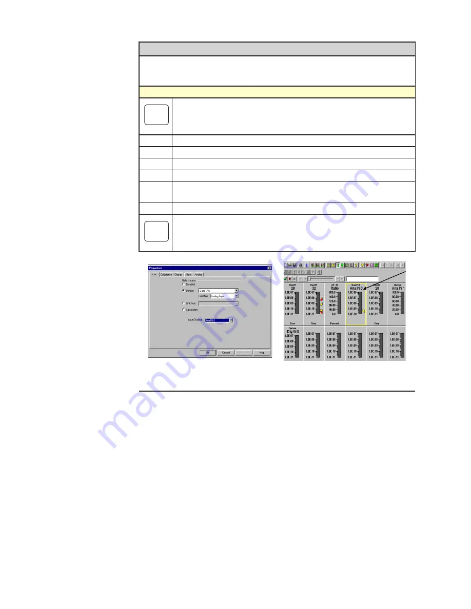
Click on the “Device” button and select the device (Figure A-8).
•
Select the “Function” and the “Input Channel.”
•
Click “OK” and the display for the I/O channel you configured will be
added to the mode screen.
•
Repeat for each input channel.
NOTE
Analog input values will range from 0 to 4095 and digital input values will
be 0 or 1.
Figure A-8.
Adding a display screen for an input channel.
Summary of Contents for Dycor Dymaxion Mass Spectrometer
Page 18: ...1 8 Dycor Dymnaxion Mass Spectrometer This page intentionally left blank...
Page 22: ...2 4 Dycor Dymaxion Mass Spectrometer...
Page 62: ...5 8 Dycor Dymaxion Mass Spectrometer This page intentionally left blank...
Page 78: ...6 16 Dycor Dymaxion Mass Spectrometer This page left blank intentionally...
Page 86: ...7 8 Dycor Dymaxion Mass Spectrometer This page intentionally left blank...
Page 90: ...7 12 Dycor Dymaxion Mass Spectrometer This page intentionally left blank...
Page 102: ...A 12 Dycor Dymaxion Mass Spectrometer This page intentionally left blank...
Page 121: ...Opto 22 Option Appendix B 19 AMETEK Part 25542JE Output Module 2 Channel Analog 0 to 10 VDC...
Page 125: ...Opto 22 Option Appendix B 23 AMETEK Part 25544JE Output Module 4 Channel Source DC 5 60 VDC...
Page 127: ...Opto 22 Option Appendix B 25 AMETEK Part 25543JE Input Module 4 Channel 2 5 28 VDC...
Page 128: ...Appendix B 26 Dycor Dymaxion Mass Spectrometer This page intentionally left blank...


