


Impulse™ Series
48
Fig. XX2 Distance
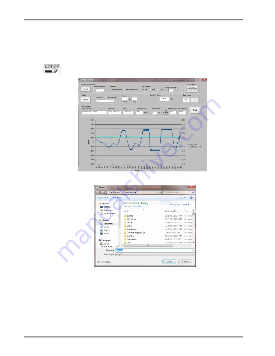
Tank Profile Data window
Tank Mapping
3.7.8 Tank Profile Data window
Clicking the View Signals button opens the tank profile screen below.
• If level is static, change Map Precision from Single to Full. This
provides the best detail of the signal but takes slightly longer to
generate a recording.
Note:
The level must not be moving for a "Full" sample or the screen
will be corrupt.
• Click the Record button. Save As window will appear. Select desired
file location type file name and click Save button.
• Recording will start and record button changes to Stop.
• First threshold line will appear as a light blue line.
• Signal will appear as dark blue line.
• Highest Signal and Max Signal Area relate to Threshold and Signal
Area respectively from Main Screen
• The reflection with the largest area that exceeds the threshold is
detected as the level.
• Record at least 5 minutes.
• Click Stop button.
• Contact Drexelbrook for further analysis of the signal.
Summary of Contents for Impulse GW Series
Page 4: ...Contents...
Page 6: ...Section 1...
Page 16: ...Section 2...
Page 25: ...Installation 19 2 6 Dual Compartment Housing...
Page 26: ...Section 3...
Page 56: ...Section 4...
Page 82: ...Impulse Series 76 5 2 1 System Dimensions Continued...
Page 83: ...Supplementary ATEX Installation Instructions 77 5 2 1 System Dimensions Continued...
Page 84: ...Impulse Series 78 5 2 1 System Dimensions Continued...
Page 86: ...Section 6...
Page 92: ...Section 7...
Page 93: ...Control Drawings 87 Section 7 Control Drawings 7 1 FM FMC Control Drawings...
Page 94: ...Impulse Series 88 7 1 FM FMC Control Drawings Continued...
Page 95: ...Control Drawings 89 7 2 ATEX Control Drawings...
Page 96: ...Impulse Series 90 7 2 ATEX Control Drawings Continued...