


Product description
38
ED 02 BAH0023.0 03.14
4
Product description
This section:
•
provides a comprehensive overview of the implement's structure
•
provides the names of the individual modules and controls.
If possible, read this section when actually at the implement. This helps
you to understand the implement better.
4.1
Main assemblies of the implement
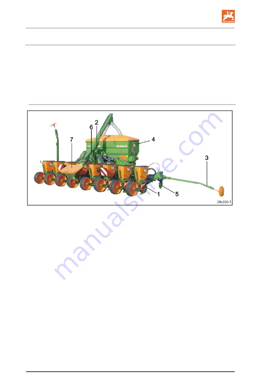
Fig. 9
Fig. 9/...
(1) Sowing unit
(2) Suction air fan
(3) Track marker
(4) 900/1100 litre fertiliser hopper (optional)
(5) Fertiliser coulter (optional)
(6) Compressed air fan (optional)
(7) Fertiliser filling auger (optional)


