6–30
Chapter 6: IP Core Interfaces
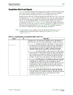
Reset Signals and Status Signals
Stratix V Hard IP for PCI Express
June 2012
Altera Corporation
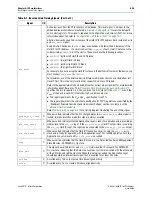
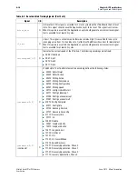
hotrst_exit
O
Hot reset exit. This signal is asserted for 1 clock cycle when the LTSSM exits the hot reset
state. This signal should cause the Application Layer to be reset. This signal is active low.
When this pulse is asserted, the Application Layer should generate an internal reset signal
that is asserted for at least 32 cycles.
l2_exit
O
L2 exit. This signal is active low and otherwise remains high. It is asserted for one cycle
(changing value from 1 to 0 and back to 1) after the LTSSM transitions from l2.idle to detect.
When this pulse is asserted, the Application Layer should generate an internal reset signal
that is asserted for at least 32 cycles.
currentspeed[1:0]
O
Indicates the current speed of the PCIe link. The following encodings are defined:
■
2b’00: Undefined
■
2b’01: Gen1
■
2b’10: Gen2
■
2b’11: Gen3
ltssmstate[4:0]
O
LTSSM state: The LTSSM state machine encoding defines the following states:
■
00000: Detect.Quiet
■
00001: Detect.Active
■
00010: Polling.Active
■
00011: Polling.Compliance
■
00100: Polling.Configuration
■
00101: Polling.Speed
■
00110: config.Linkwidthstart
■
00111: Config.Linkaccept
■
01000: Config.Lanenumaccept
■
01001: Config.Lanenumwait
■
01010: Config.Complete
■
01011: Config.Idle
■
01100: Recovery.Rcvlock
■
01101: Recovery.Rcvconfig
■
01110: Recovery.Idle
■
01111: L0
■
10000: Disable
■
10001: Loopback.Entry
■
10010: Loopback.Active
■
10011: Loopback.Exit
■
10100: Hot.Reset
■
10101: LOs
ltssmstate[4:0]
(continued)
O
■
11001: L2.transmit.Wake
■
11010: Speed.Recovery
■
11011: Recovery.Equalization, Phase 0
■
11100: Recovery.Equalization, Phase 1
■
11101: Recovery.Equalization, Phase 2
■
11110: recovery.Equalization, Phase 3
Table 6–7. Reset and Link Training Signals (Part 3 of 3)
Signal
I/O
Description

