


Chapter 5: IP Core Architecture
5–7
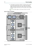
Data Link Layer
June 2012
Altera Corporation
Stratix V Hard IP for PCI Express
■
PCI Power Management Capability Structure
■
Virtual Channel Capability Structure
■
Message Signaled Interrupt (MSI) Capability Structure
■
Message Signaled Interrupt–X (MSI–X) Capability Structure
■
PCI Express Capability Structure
■
Advanced Error Reporting (AER) Capability Structure
■
VSEC
The Configuration Space also generates all messages (PME#, INT, error, slot power
limit), MSI requests, and completion packets from configuration requests that flow in
the direction of the root complex, except slot power limit messages, which are
generated by a downstream port. All such transactions are dependent upon the
content of the PCI Express Configuration Space as described in the
f
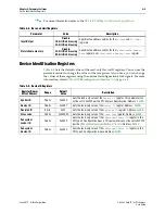
Refer To
“Configuration Space Register Content” on page 7–1
Express Base Specification 2.1
for the complete content of these registers.
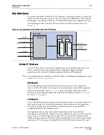
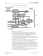
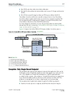
Data Link Layer
The Data Link Layer (DLL) is located between the Transaction Layer and the Physical
Layer. It is responsible for maintaining packet integrity and for communication (by
DLL packet transmission) at the PCI Express link level (as opposed to component
communication by TLP transmission in the interconnect fabric).
The DLL is responsible for the following functions:
■
Link management through the reception and transmission of DLL packets (DLLP),
which are used for the following functions:
■
For power management of DLLP reception and transmission
■
To transmit and receive
ACK
/
NACK
packets
■
Data integrity through generation and checking of CRCs for TLPs and DLLPs
■
TLP retransmission in case of
NAK
DLLP reception using the retry buffer
■
Management of the retry buffer
■
Link retraining requests in case of error through the Link Training and Status State
Machine (LTSSM) of the Physical Layer