


Rockwell Automation Publication 1444-UM001D-EN-P - June 2018
143
Measurement Definition
Chapter 4
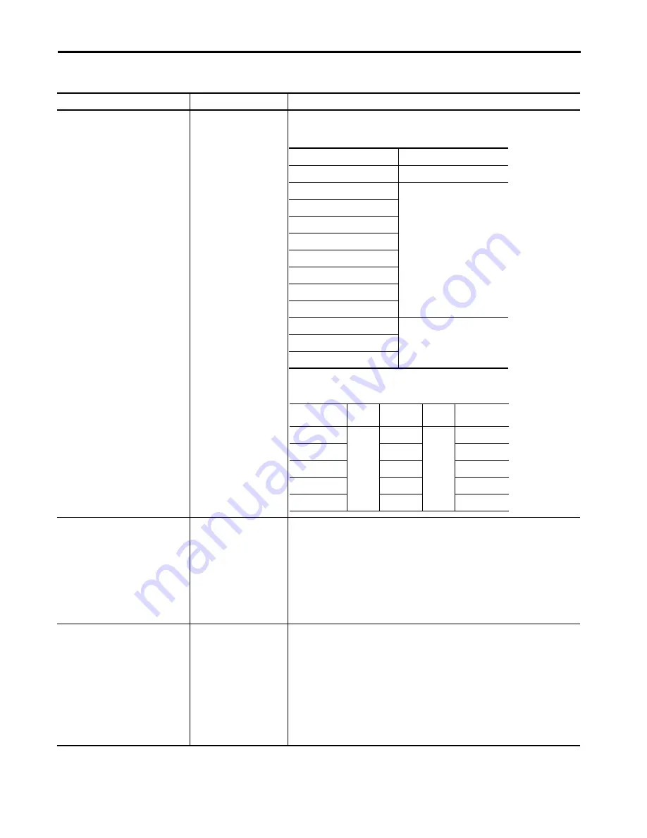
Measurement Units
See Help comments
Select the Engineering Units for the Tracking Filter measurements. These measurements are the
units that are applied to all enabled tracking filters for the channel.
The rules for Units selection, which is based on the Xdcr Units, are provided in the following table.
For any acceleration, velocity or displacement (length) units the measurement can include any
required integration (or differentiation) simply by selecting the appropriate output units.
Signal Detection
Select from:
• Peak
• Peak to Peak
• RMS
Select the signal detection method for all Tracking Filter magnitude measurements for this
channel.
A Tracking Filter is measured over a number of cycles or shaft revolutions, not from an
instantaneous sample. It isn’t possible to measure the actual “true” deflection of any single cycle.
Consequently, the selections are (scaled) Peak, (scaled) Peak to Peak, and RMS.
However, if the filtered signal is such that only the sine-wave of the order of interest remains, then
the “scaled” RMS equates to the “true” peak, or peak to peak measurement. The key difference
remains that the Tracking Filter is resolved from an extended data set, so the result does not equate
to the “true” peak or peak to peak measure of a signal that is not consistent throughout the
sample.
Measurement Resolution Speed 0/1
1…256
Enter the number of revolutions (bandwidth) to be applied to all tracking filters on this channel
that are defined for use with this tacho (0/1).
• The Number of Revolutions (over which the order results are calculated) determines the
narrowness of the filter, with more revolutions resulting in a sharper/narrower, more effective,
filter. However:
– A high number of revolutions results in an accurate measurement of the specified order.
However, at low speeds a high number of revolutions settings can slow the measurement
response to changes.
– A low number of revolutions results in a broad filter that passes signals other than the
specified order value. However, the lower the number of orders the more responsive it is to
changes.
• A typical value is 10 (the default). A high value is 30, but values up to 256 are possible.
Table 29 - Tracking Filters (continued)
Parameter
Values
Comment
CLASS
CHANGE EU OPTION
Temperature
No change
Pressure
Change in class only
Flow
Angle
Current
Energy
Frequency
Power
Voltage
Acceleration
Selections per following table
Velocity
Length
Displacement
Velocity
Acceleration
m
m/s
m/s
2
mm
mm/s
mm/s
2
micron
inch/s
inch/s
2
inch
g
mil
mg