8 • Schlage • SFIC service manual
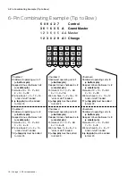
If You Are Not Familiar With Pinning Best Style Cores
If You Are Not Familiar With Pinning Best Style Cores
1. Never remove the plug! These cores are designed to be
top loaded. All combinating is done strictly by numbers
as it is not possible to see any of the pins at the shear
line. Each pin size is determined with simple addition
and subtraction. There is no opportunity for trial-and-
error.
Top Pin
Build-up Pin
Master Pin
Bottom Pin
2. For all operating keys, have the bittings legibly and
neatly written. You can get bittings from the bittings list
or by gauging each key individually. Each digit of the
control key should be directly over the corresponding
digit of the master and change key. With the control
key bitting on the top, it is helpful to draw a line under it
in order not to confuse control bittings with operating
bittings during the pin calculation.
Unless the core is cross keyed, you normally only need
three key bittings: control, TMK (top master key) and
change key. In most properly designed systems,
intermediate level master keys will operate
automatically. This is because each digit of their bitting
is usually contained either in the TMK or the change key.
If any master keys must operate which have a digit not
already contained in the change or TMK, that digit must
be written in the appropriate position and pinned in.
3. Insert any key, turn the plug about 90° and remove the
key. Be sure the control lug remains extended, leaving a
clear passage down the pin chambers to the plug
surface.
Check for uniform
space here
Turn plug
about 90
Control lug
extended
4. There are two shear lines in each chamber; one for the
operating keys (change, master, grand master, etc.) and
one for the control key. A build-up pin is used to span
the distance between the two. Its length changes
based on the difference between the control key and
the deepest operating key.
The pin stack is illustrated below, together with the
addition and/or subtraction necessary to determine
each pin. All chambers use exactly the same logic and
math. They differ only by the specific bitting number of
each key in a given cut position.
5. Combinate one chamber completely before moving on
to the next. Think of each one as a simple math
problem which always has the answer of 23. Many
beginners try to install all seven bottom pins, then all
master pins, then all build-up pins, etc. This method
may seem easier but it forces you to think through each
“math problem” two or three times, rather than once.
Mistakes are more common with this method. You will
also never pick up any speed this way and will usually
have to write down all the pins before combinating the
core. Your goal should be to calculate each chamber
quickly in your head as you build each stack.
6. In a master keyed core, each chamber normally has four
pins. With the plug turned, you can watch the top
surface of each pin stack as you complete it. The top
surfaces should all line up evenly, about .050” below
the top surface of the core. Paying attention to this
detail lets you spot a pinning error immediately and
correct it before it’s too late.
Operating Key
Control Key
BU
BU
Summary of Contents for Schlage D Series
Page 1: ...Schlage Manuals 2016...
Page 2: ...D Series Service manual...
Page 3: ......
Page 4: ......
Page 5: ......
Page 6: ......
Page 7: ......
Page 8: ......
Page 9: ......
Page 10: ......
Page 11: ......
Page 12: ......
Page 13: ......
Page 14: ......
Page 15: ......
Page 16: ......
Page 17: ......
Page 18: ......
Page 19: ......
Page 20: ......
Page 21: ......
Page 22: ......
Page 23: ......
Page 24: ......
Page 25: ......
Page 26: ......
Page 27: ......
Page 28: ......
Page 29: ......
Page 30: ......
Page 31: ......
Page 32: ......
Page 33: ......
Page 34: ......
Page 35: ......
Page 36: ......
Page 37: ......
Page 38: ......
Page 39: ......
Page 40: ......
Page 41: ......
Page 42: ......
Page 43: ......
Page 45: ...Schlage small format cores Service manual...
Page 46: ......
Page 48: ......
Page 49: ...Schlage SFIC service manual 5...
Page 58: ......
Page 59: ......
Page 62: ......
Page 64: ......
Page 107: ......
Page 109: ...Everest full size cylinder Service manual...
Page 110: ......
Page 129: ...B Series Service manual...
Page 130: ......
Page 150: ...22 Schlage B Series service manual Locks...
Page 165: ...Options and Parts Schlage B Series service manual 37 Notes...
Page 166: ...38 Schlage B Series service manual Options and Parts Notes...
Page 167: ......
Page 169: ...ND Series Service manual...
Page 270: ...L Series Service manual...
Page 271: ......
Page 293: ...24 Schlage L Series service manual...
Page 359: ...90 Schlage L Series service manual...
Page 444: ...Schlage L Series service manual 175...
Page 499: ...230 Schlage L Series service manual...
Page 500: ......
Page 502: ...AL Series Service manual...
Page 503: ......
Page 505: ......
Page 542: ...A Series Service manual...
Page 543: ......
Page 545: ......
Page 572: ......

